 |
|||
|
|
|||
|
Page Title:
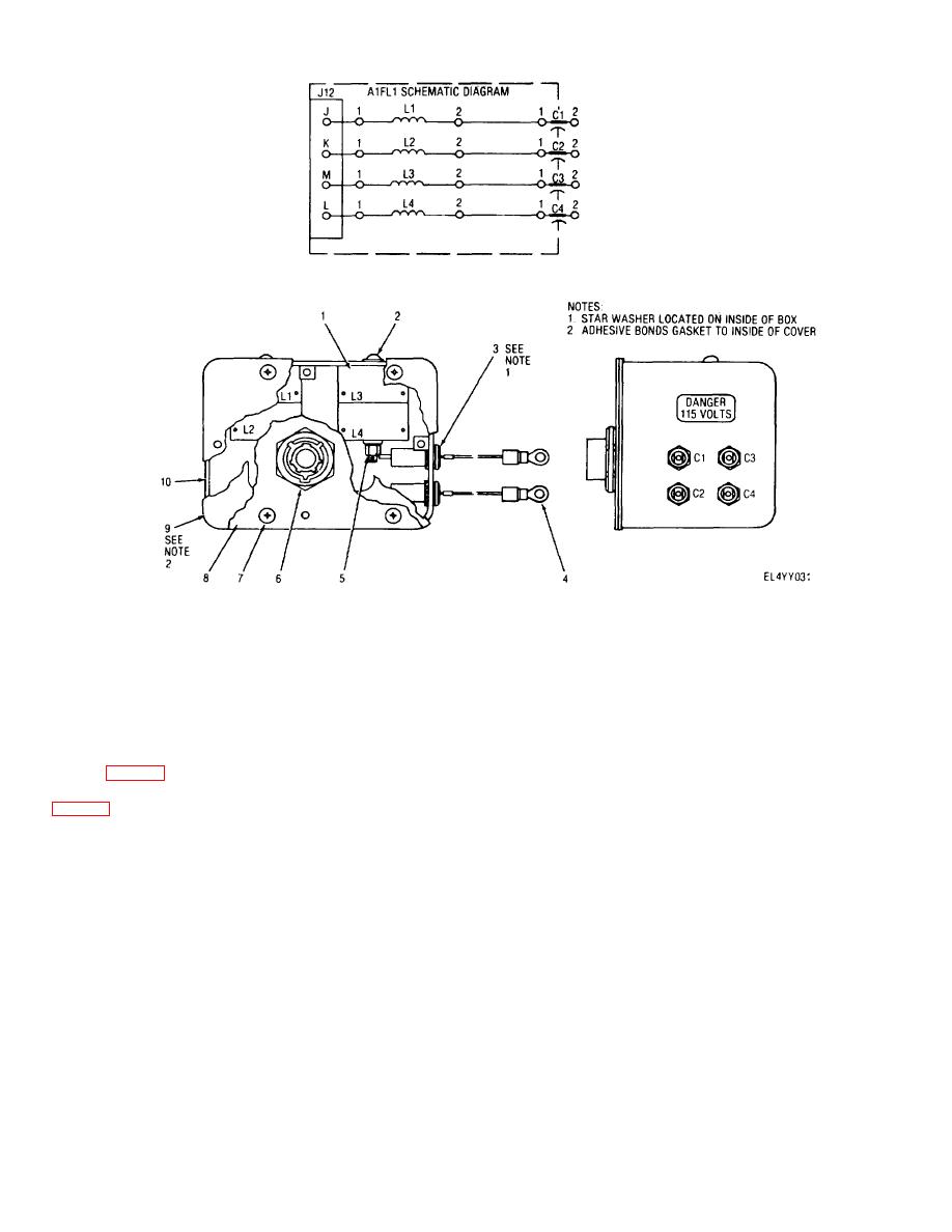
Figure 5-4. Filter assembly A1FL1 parts location and schematic diagram. |
|
||
| ||||||||||
|
|
 TM 11-6625-2937-13
1.
Reactor, toroid, 500 mh (L1 through L4)
6. Connector (J12)
2.
Screw, 8-32 x 2, No. 8 flat washer (2 places)
7. Screw, 6-32 x 3/8 (4 places)
3.
Capacitor, 0.01 of 600 V dc (C1 through C4)
8. Cover
4.
Terminal, crimp (3 Places)
9. Gasket
5.
No. 8 Flatwasher, No.8 lockwasher, No. 8 nut (2 places)
10. Housing
Figure 5-4. Filter assembly A1FL1 parts location and schematic diagram.
5-18. Removal and Replacement of Power Supply
CAUTION
A1PS1 (fig. 5-3)
Hold power supply AIPSI securely to prevent
a. Removal. Remove power supply AI PS2 (7,
damage
to
adjacent
hardware
while
performing steps (6) and (7).
(6) Remove four nuts (12) and associated
WARNING
washers securing power supply A1PS1 to rear panel of
Ensure all power is disconnected from equipment.
control-interface unit.
(7) Remove power supply A1PS1 being careful
(1) Remove top and bottom access covers from
to clear rear panel.
control-interface unit (para 5-14a).
Place control-
b. Replacement. Replace power supply A IPSI as
interface unit on its left side.
follows:
(2) Locate power supply AIPSI (7) on rear panel
(1) Verify that base of power supply A1IPS1I (7) and
and tag wires connected to its four terminals (five wires).
mounting surface on rear panel are completely coated
(3) Unsolder wires tagged in step (2) from
with silicone heat sink compound. Apply silicone heat
power supply A1PS1terminals and place carefully aside.
sink compound (Dow Corning 340) as required to
(4) Loosen four screw lock assemblies (8)
uncoated areas.
securing connectors P1 (9) and P2 (10) to 115 and J16,
(2) Position
replacement
power
supply
respectively, on circuit card assembly rack 1A2 (11).
A1PS1on mounting surface of rear panel. Secure in
(5) Disconnect connectors Pi and P2 from J15
place with four nuts (12) and associated washers.
and J16, respectively, and set aside carefully.
(3) Reconnect wires to four terminals of A1PS1
5-13
|
|
Privacy Statement - Press Release - Copyright Information. - Contact Us |
