 |
|||
|
|
|||
|
Page Title:
SECTION III. TECHNICAL PRINCIPLES OF OPERATION |
|
||
| ||||||||||
|
|
 TM 11-6625-2885-12/NAVAIR 16-35TS3614-1
SECTION
III
TECHNICAL
PRINCIPLES
OF
OPERATION
BLOCK
DIAGRAM
DESCRIPTION
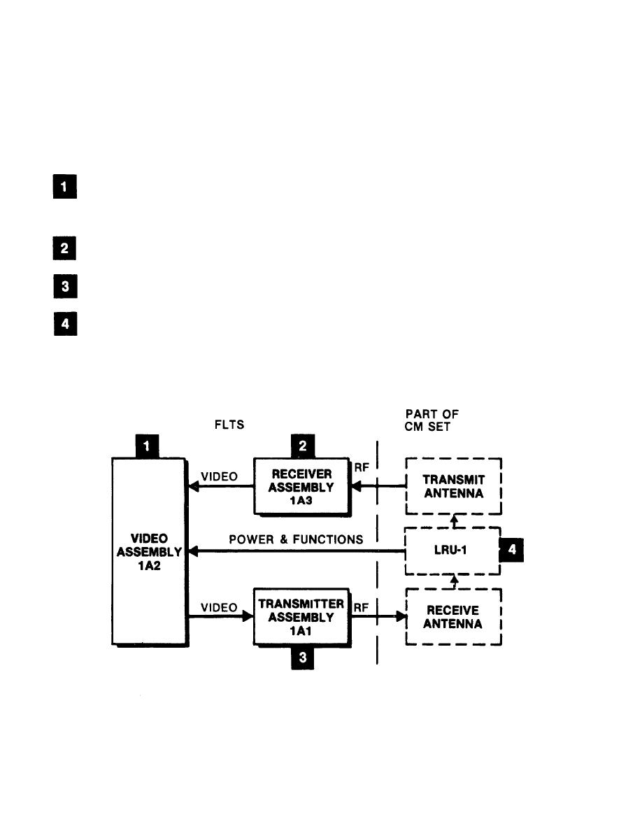
1-14. This section gives you a block diagram keyed to a functional description
of the FLTS.
Video assembly 1A2 receives video signals from the FLTS receiver assembly.
I t generates modulating signals and transmits them to the FLTS transmitter
assembly. During self-test it controls the test and visually indicates
results.
Receiver assembly 1A3 receives an RF signal from the CM set, detects the
RF power threshold and routes it to video assembly 1A2.
Transmitter assembly 1A1 furnishes the CM set receive antenna with an RF
signal modulated with the video signals generated in the video assembly.
Operating power and functions are furnished to the FLTS directly from
LRU-1.
1-12
|
|
Privacy Statement - Press Release - Copyright Information. - Contact Us |