 |
|||
|
|
|||
|
|
|||
| ||||||||||
|
|
 TM 11-6625-2884-30/NAVAIR 16-35TS3615-2
Increase gain and use off-
set as necessary. Increase
INPUT RF ATTENUATOR by
CS MOD DEPTH setting. observe
modulation peak.
Modulation sinewave
will appear distorted
on oscilloscope because
of video detector.
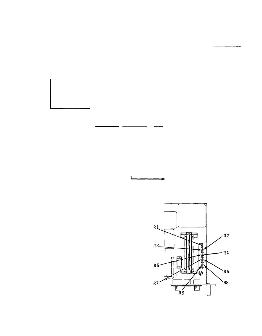
CS MOD DEPTH and 1A2
Attenuation Tolerance.
Set
Tolerance
Mod Depth
O.1
dB
R9
R8
1
dB
O.2
dB
R7
3
dB
0.3
dB
0.6
dB
6
dB
R6
R5
0.9
dB
9
dB
R4
12
dB
1.0
dB
R3
1.0
dB
15
dB
20
dB
1.O
dB
R2
1.0
dB
25
dB
R1
As in step 7 except
adjust the correspond-
ing potentiometer (SET).
11.
Disconnect W5 from
1A3 RF OUT and recon-
nect to 1A4 RF OUT.
Connect oscilloscope
external sync to 1A4
sync CS. Set 1A3 CS
MOD DEPTH to O and
1A3 VAR PRI to OFF.
Set 1A4 CS MOD DEPTH
to 9 dB. Repeat steps
1-10 above.
END OF TEST
3-35
|
|
Privacy Statement - Press Release - Copyright Information. - Contact Us |
