 |
|||
|
|
|||
|
|
|||
| ||||||||||
|
|
 TM 11-862S-2884-30/NAVAIR l6-35TS3615-2
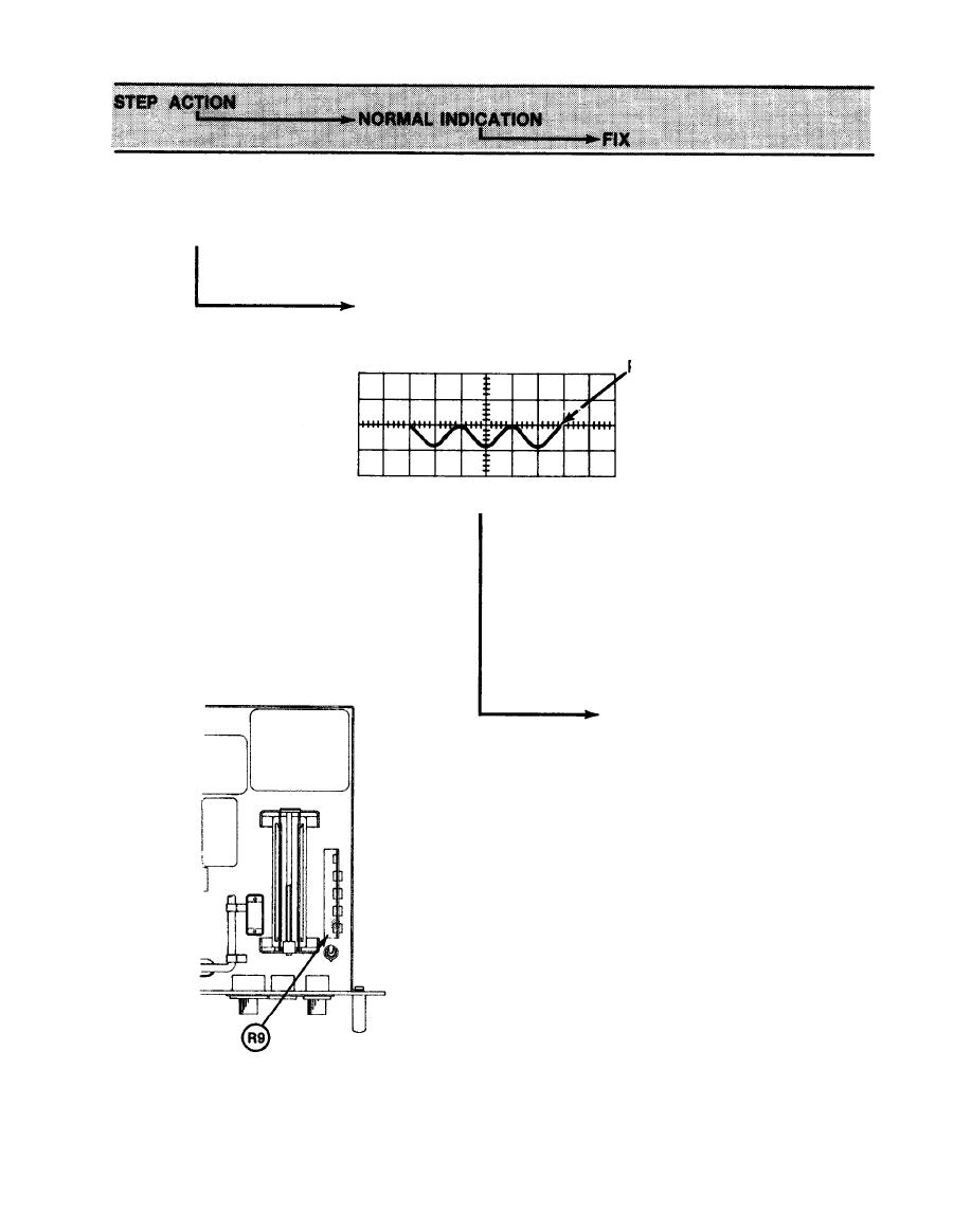
7. Add 1 dB to the 1A2
attenuator and
observe.
Modulation peak point
is now on the same refer-
ence line 0.2 DIV.
PEAK POINT
0.2 VOLTS/DIV
(1000 ohms termi nation)
SWEEP :
2.0 ms/DIV
CAUTION
Before moving 1A3 or 1A4 assemblies,
remove back cover and disconnect
coaxial RF cables. Moving these
assemblies without disconnecting
coax cables may damage cables.
CAUTION
Loosen four front panel
mounting bolts (1A3).
Gently slide 1A3 forward
for access. Use a thin
screwdriver to adjust
potentiometer 1A3A3R9 on
chassis until minimum
point is on reference
line.
Replace 1A3A2 cir-
a.
cuit card. If no
improvement is
noted, reinstall
original circuit
card.
b.
Replace RF Modula-
tion Assembly 1A3.
3-33
|
|
Privacy Statement - Press Release - Copyright Information. - Contact Us |