 |
|||
|
|
|||
|
|
|||
| ||||||||||
|
|
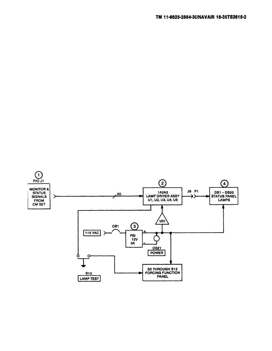 c. Status.
(1) A total of 18 status signals and 2 spares are supplied from LRU-1
to the BTS to monitor the status of LRU-1. The signals are
monitored by indicator lights. The status signal, negative logic
is connected from LRU-1 Jack J7 through Cable W1 to Jack J1 on the
status panel.
(2) LAMP DRIVER ASSY 1A2A3 (U1, U2, U3, U4, U5) receives the status
signals from J1. The status signals are connected to five
identical integrated circuit chips. Each chip contains four lamp
driver circuits. Each driver consists of a two-input nand gate and
output power driver.
(3) Power Supply PS1 supplies +12 Volts to one terminal of al 1 status
panel lamps.
(4) Whenever the inverting output power driver receives a positive
logic 1 signal, that particular status panel lamp illuminates. The
following is a simplified circuit of the U1 lamp driver and status
lamp DS1.
2-39
|
|
Privacy Statement - Press Release - Copyright Information. - Contact Us |
