 |
|||
|
|
|||
|
|
|||
| ||||||||||
|
|
 TM 11-8625-2884-30/NAVAIR 16-35TS3615-2
RF MODULATION
2-4. (Refer to figure FO-3.) The RF modulation functions will be discussed in
the following sections as in figure FO-3.
q RF Path
q Digital
Circuits
Analog Circuits
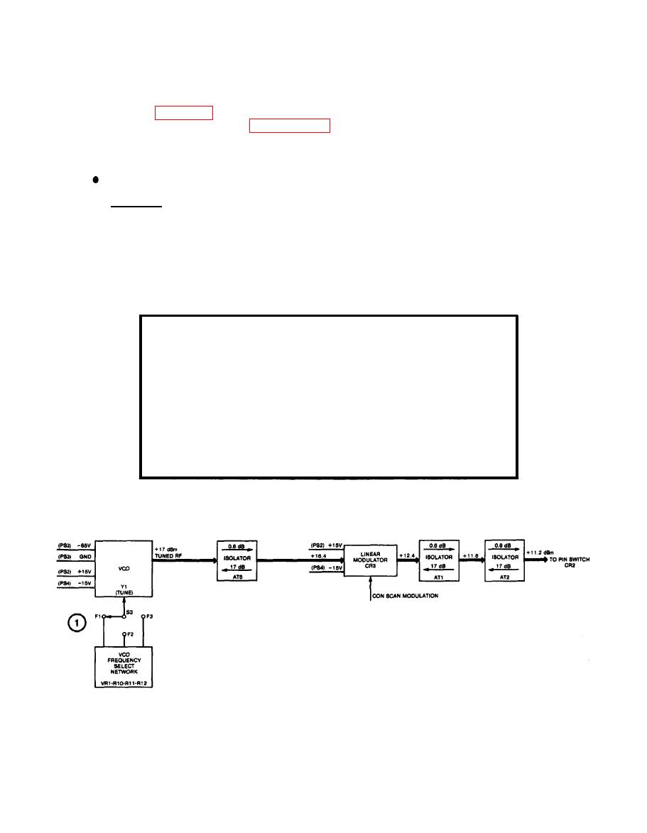
a. RF Path.
(1) The VCO frequency select network consists of three adjustable poten-
tiometers R1O, R11, R12 and diode VR1. The potentiometers are
adjusted to tune VCO (Y1) to three fixed RF frequencies, selected by
frequency select switch S3. The following chart specifies the switch
position-, and potentiometer adjusted.
S3-Switch Position
Potentiometer Adjusted
F1
R12
F2
R11
F3
R10
The output of the VCO is approximately +17 dBm.
2-23
|
|
Privacy Statement - Press Release - Copyright Information. - Contact Us |
