 |
|||
|
|
|||
|
Page Title:
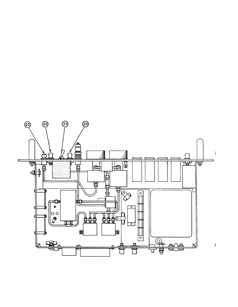
Status Panel Assembly 1A2 (Top View). (cont) |
|
||
| ||||||||||
|
|
 TM 11-6625-2884-30/NAVAIR 16-35TS3615-2
LOCATION AND DESCRIPTION OF MAJOR COMPONENTS (Continued)
(20) J4 - CHAN 1 - Connects to oscilloscope to monitor 17 test points in
LRU-1 under test or 1 signal from BTS, controlled by the OSCILLOSCOPE
MONITOR Switch S1 (21) and UUT SIGNAL/DET VIDEO Switch S3.
(21) S1 - OSCILLOSCOPE MONITOR - Dual concentric rotary switch. Black
knob switches CHAN 1 (20) connector to 1 of 17 points in the LRU-1
under test or to BTS 1 VIDEO J7 (9). Red knob switches CHAN 2 (22)
connector to 1 of 17 points in LRU-1 under test or to BTS 2 VIDEO J8
(lo).
(22) J5 - CHAN 2 - Connects to oscilloscope to monitor 17 test points in
LRU-1 under test or 1 signal from BTS.
- Connects
to RF output of LRU-1 under test.
(23) J2 - RF IN
1-26
|
|
Privacy Statement - Press Release - Copyright Information. - Contact Us |