 |
|||
|
|
|||
|
Page Title:
Status Panel Assembly 1A2 (Top View). (cont) |
|
||
| ||||||||||
|
|
 TM 11-6625-2884-30/NAVAIR 16-35TS3615-2
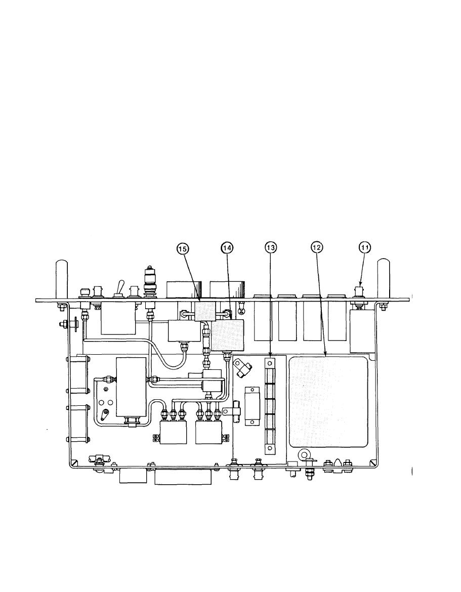
LOCATION AND DESCRIPTION OF MAJOR COMPONENTS (Continued)
J6 - JACK - Connects to voltage point in LRU-1 under test selected by
(11)
the voltage monitor switch S2. (15)
PS1 - POWER SUPPLY - Supplies +12 Vdc to status signal, and forcing
(12)
function lamps.
A3 - LAMP DRIVER ASSY - Provides a ground return to status signal
(13)
lamps, when enabled by LRU-1 under test.
AT2 - INPUT RF ATTENUATOR - Controls RF output level at VAR RF OUT
(14)
Connector J3 in 0-60 dB steps.
S2 - VOLTAGE MONITOR - Monitors dc voltages in the LRU-1 under test.
(15)
1-24
|
|
Privacy Statement - Press Release - Copyright Information. - Contact Us |