|
| |
TM 55-6695-220-13&P
a.
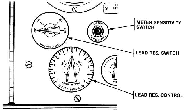
The indicator manual is consulted to determine the lead resistance, and the tester's LEAD RESISTANCE
SWITCH is set to match this standard resistance of either 2, 8 or 22 OHMS. The LEAD RESISTANCE CONTROL is
rotated both clockwise and counterclockwise until the VOLTMETER pointer is positioned directly over the zero mark.
This process is continued while the METER SENSITIVITY SWITCH is depressed, allowing a more accurate setting of the
LEAD RESISTANCE CONTROL.
b.
The final position of the pointer is the error in ohms either high or low by which the lead resistance differs from
the established standard. Note resistance discrepancy and reverse position of red and black clip leads on lead terminals
and repeat above procedures to obtain a second resistance error. The average of the two readings becomes the true
error for each temperature setting. Return the LEAD RESISTANCE SWITCH to the OFF position before disconnecting
the clip leads. Turn the RESISTANCE AND VOLTAGE FUNCTION SWITCH to the OFF position at the completion of
each test in order to conserve battery energy.
2-3.
RESISTANCE THERMOMETER INDICATOR TEST PROCEDURES.
2-3
a.
Disconnect the resistance thermometer transmitter from the indicator by unscrewing the circular connector
located at the back of the indicator. Consult the manual for information regarding whether the indicator is a single or
dual, and whether 12 or 24 volt transmitter excitation voltage is required.
2-8
|