|
| |
TM 55-4920-400-13
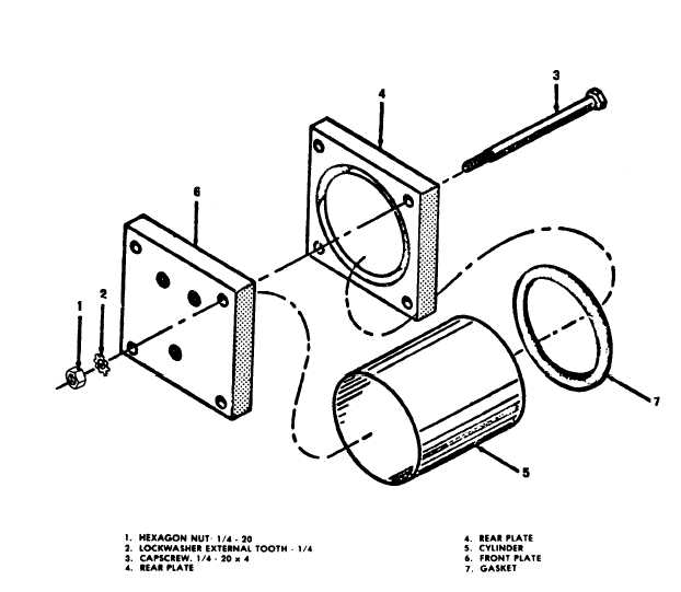
Figure 2-4. Oil reservoir, exploded view.
2-51. Fill and Run Selector Valve. The selector
and oil reservoir.
valve is removed and replaced as follows:
b. Installation.
a. Removal.
(1) Install pipe nipple on selector valve and oil
(1) Remove oil reservoir from chassis as in-
reservoir.
strutted in paragraph 2-50.
(2) Install oil reservoir on chassis as in-
(2) Remove pipe nipple from selector valve
strutted in paragraph 2-46.
2-13
|