|
| |
2-12
TM 55-4920-400-13
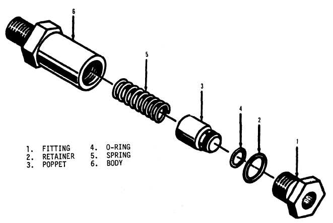
Figure 2-3. Check valve, exploded view.
(3) Replace valve if defective.
ll
c. Instalation.
(1) Place relief valve in position on chassis
and secure with screws, lockwashers, and nuts.
(2) Install tube assembly, pipe tees, elbows,
and pipe nipple on the relief valves.
(3) Install pressure filter sump as instructed
in paragraph 2-47.
(4) Install chassis assembly in tester case,
paragraph 2-46.
2-50. Oil Reservoir. Remove the oil reservoir
from the chassis to replace and disassemble for
cleaning and repair as follows:
a.. Removal.
(1) Remove chassis assembly from tester case
(para. 2-46),
(2) Remove hose assembly from elbow and re-
move cap and tube nipple from hose assembly.
(3) Remove tube assemblies.
(4) Remove pressure check Valve and elbow
from oil reservoir.
(5) Remove screws and lockwashers securing
oil reservoir to Chassis. Remove oil reservoir.
(6) Remove pipe nipple and selector valve
from oil reservoir.
b. Disassembly. The oil reservoir is disassem-
bled in the sequence of the index numbers (fig. 2-4).
c. Cleaning and Inspection.
(1) Clean the parts, except the gaskets, with
cleaning solvent, Federal Specification P-D-680 or
equivalent, and dry thoroughly.
(2) Inspect the parts for cracks, breaks, deteri-
oration, and damaged threads.
(3) Replace defective parts from AVIM stock.
d. Reassembly. The oil reservoir is reassembled
in the reverse sequence of the index numbers (fig. 2-
4).
e. Installation.
(1) Install pipe nipple and selector valve on oil
reservoir.
(2) Place oil reservoir in position on chassis
and secure with lockwashers and screws
(3) Install elbow and pressure check valve on
oil reservoir.
(4) Install tube assemblies.
(5) Install chassis assembly in tester case
(para. 2-46).
|