 |
|||
|
|
|||
|
Page Title:
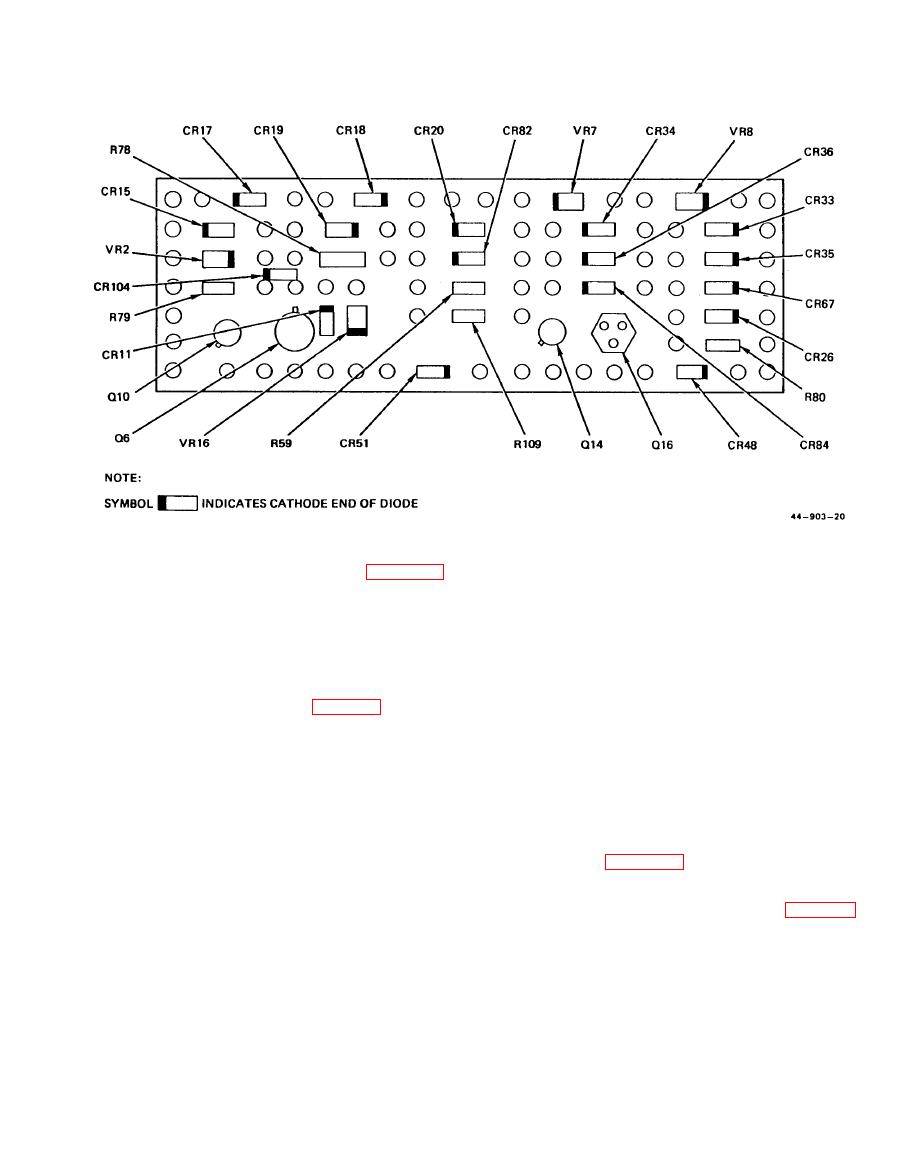
Figure 8-8. Electronic Component Assembly No. 2 A2 Parts Location Diagram |
|
||
| ||||||||||
|
|
 ARMY TM 5-6675-309-14
MARINE CORPS TM 08840A-14/1
curing connector J1 (52) to PSTS front
1. Place PSTS front panel (51, figure 8-6,
panel (51).
sheet 1) in PSTS instrument case (1).
Align mounting holes.
Replace wires on connector J1 (52).
3.
2. Install 20 screws (49) and washers (50)
4.
Place PSTS front panel (51) in PSTS in-
securing PSTS front panel (51) to PSTS
strument case (1). Align mounting holes.
instrument case (1).
Install 20 screws (49) and washers (50)
5.
(36) Connectors J1 thru J7. Remove and replace
securing PSTS front panel (51) to PSTS
typical connector J1 (52, figure 8-6, sheet 1) as
instrument case (1).
follows:
e. PSTS Adjustments. The PSTS adjustments con-
(a) Removal.
sist of adjusting two modular power supplies to their
Remove 20 screws (49) and washers (50)
1.
specified output voltage, adjusting two timer circuits to
securing PSTS front panel (51) to PSTS
their specified times, and adjusting a current limiter
instrument case (1). Remove PSTS front
circuit. All adjustments should be performed every 90
panel far enough to provide access to
days. Make sure +28V power source is turned off.
connector J1 (52) .
Connect the PSTS to the +28V power source with
cable W311 (see figure 8-4). Check that polarity is
2.
Tag and remove wires from connector J1
correct. Connect cable W301 connector P2 to PSTS con-
(52). (Do not unsolder wires from lug.)
nector J3 and cable W302 connector P2 to PSTS connector
Remove four nuts (55), washers (54),
3.
J2. Leave other end of cables disconnected. See figure 8-9
screws (48), and one terminal lug W13
for location of adjustments and perform adjustment pro-
(53) securing connector J1 (52) to PSTS
cedures in accordance with the following paragraphs.
front panel 51). Remove connector.
(b) Replacement.
(1) Modular power supply PS1 voltage adjustment.
1.
Replace connector J1 (52) in PSTS front
Perform voltage adjustment of modular power
panel (51).
supply PS1 as follows:
2.
Install four screws (48), washers (54), nuts
(a) Turn on +28V power source and set IN-
PUT POWER PSTS circuit breaker to ON.
(55), and one terminal lug W13 (53) se-
Change 1
|
|
Privacy Statement - Press Release - Copyright Information. - Contact Us |
