 |
|||
|
|
|||
|
Page Title:
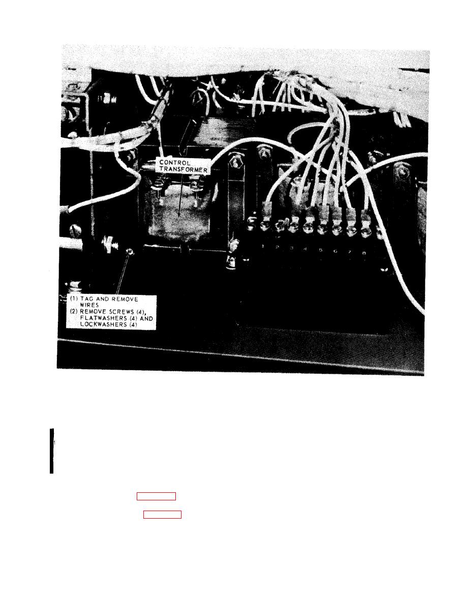
Figure 5-8. Control transformer, removal and installation. |
|
||
| ||||||||||
|
|
 TM 5-6625-2691-13&P
Figure 5-8. Control transformer, removal and installation.
TS 025344
a. Removal. Disconnect all wires from the voltage
a. Both Model A427 and Model A427B use
plug and tag them as necessary.
three each, single phase control transformers,
b. Installation. Connect all necessary wires to the
designed to supply necessary power to operate the
voltage plug and remove all tags.
fan motors and the input contactor. Although the
Model A427 and Model A427B control trans-
formers supply a similar function, they are not
interchangeable.
a. General. Three duct-type 11 kilowatt power absor-
bers provide the resistive loads. Integral fans cool the
control transformer.
absorbers by drawing air through the circular ducts.
Air switches are provided to cut off the load if the air
control transformer.
Change 1 5-9
|
|
Privacy Statement - Press Release - Copyright Information. - Contact Us |
