 |
|||
|
|
|||
|
Page Title:
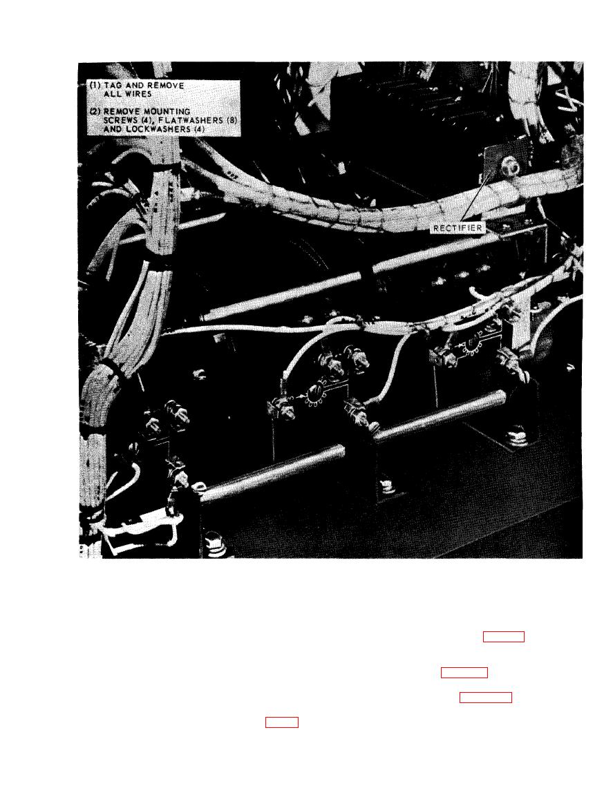
Figure 6-4. Rectifier, removal and installation. |
|
||
| ||||||||||
|
|
 TM
5-6625-2691-13&P
continuity using a multimeter (para 7-2). Check for
proper operation. Replace a defective variabl
a. General. A three gang 240/20 volt variable
transformer.
transformer is provided to control the load from 0 to 3
KW. The variable transformer is operated by control
ble transformer.
knob located on the control panel. Used in conjunction
d. Installation. Refer to figure 5-5 and install the
with various load settings, any kilowatt loading be-
variable transformer.
tween 0.5 and 33 KW can be obtained.
b. Testing. Test the variable transformer (fig. 5-5) for
|
|
Privacy Statement - Press Release - Copyright Information. - Contact Us |
