 |
|||
|
|
|||
|
Page Title:
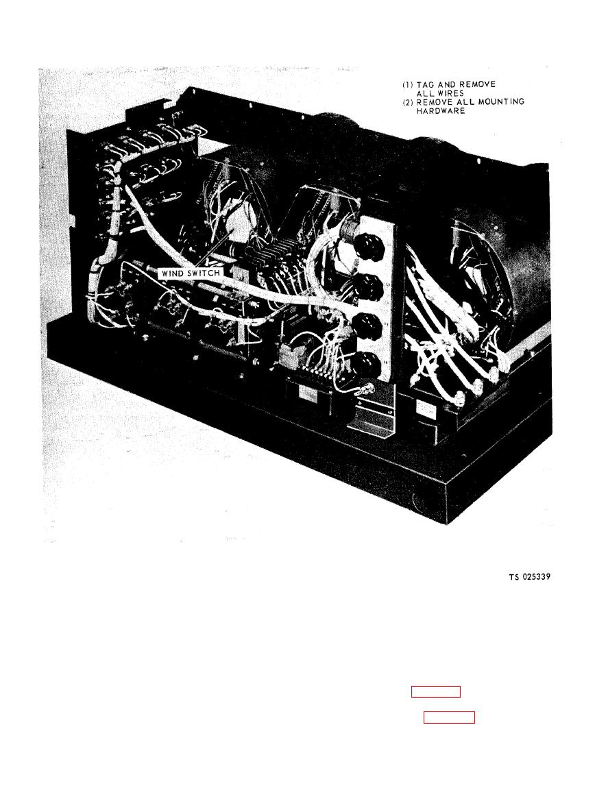
Figure 5-3. Wind switch removal and installation. |
|
||
| ||||||||||
|
|
 TM 5-6625-2691-13&P
The combined output capacity of the rectifier is 6
5-9. Rectifier
AMPS DC with air flow of 300 LFPM (Linear Feet per
WARNING
Minute). Unit is especially designed to withstand in
Do not breathe fumes of burning
--
rush of three fan motors.
selenium rectifier. Fumes are toxic
and dangerous.
tifier.
a. General. The selenium rectifier stack is an assem-
bly of twelve, triple density selenium single plate cells
tifier.
connected to form two three-phase full-wave bridges.
|
|
Privacy Statement - Press Release - Copyright Information. - Contact Us |
