 |
|||
|
|
|||
|
Page Title:
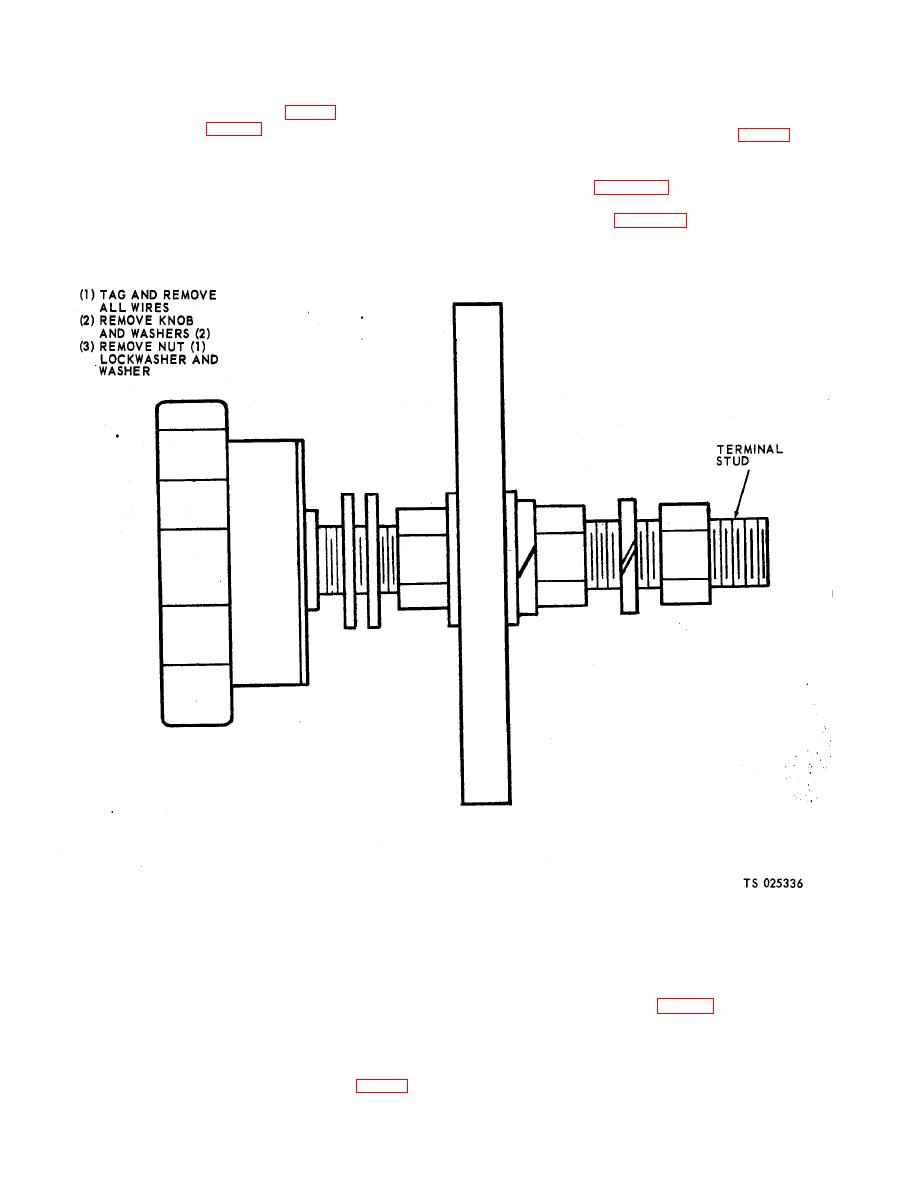
Figure 4-7. Terminal studs, removal and installation. |
|
||
| ||||||||||
|
|
 TM 5-6625-2691-13&P
a. Testing. Test the rectifier (fig. 1-2) for continuity
4-26. Terminal Stud
using a multimeter (para 7-2).
a. General. Four stud type terminals (fig. 1-3) are
supplied together with one copper shorting link which
b. Inspecting and Cleaning. Inspect the rectifier for
tie the studs together for single phase operation.
burn marks, breaks or other damage. Clean with
b. Removal. Using figure 4-5 as a guide, remove the
filtered compressed air.
terminal studs.
c. Removal and Installation. Notify direct support
maintenance for replacement.
terminal studs.
4-27. Variable Transformer
tion if the incoming voltage does not conform to the
a. Inspecting and Cleaning. Inspect track and brush
voltage connection of the test set.
for burns, unit for cracks or other damage. Clean with
b. Testing. Test the voltage sensing module for con-
filtered jet or air.
tinuity using a multimeter (para 7-2).
b. Removal and Installation. Notify direct support
c. Inspecting and Cleaning. Inspect the module for
maintenance for replacement.
visual signs of damage. Clean with compressed filtered
air.
4-28. Voltage Sensing Module
a. General. The voltage sensing module (fig. 1-3) is
d. Removal and Installation. Notify direct support
supplied to open the control circuit and prevent opera-
maintenance for replacement.
|
|
Privacy Statement - Press Release - Copyright Information. - Contact Us |
