 |
|||
|
|
|||
|
Page Title:
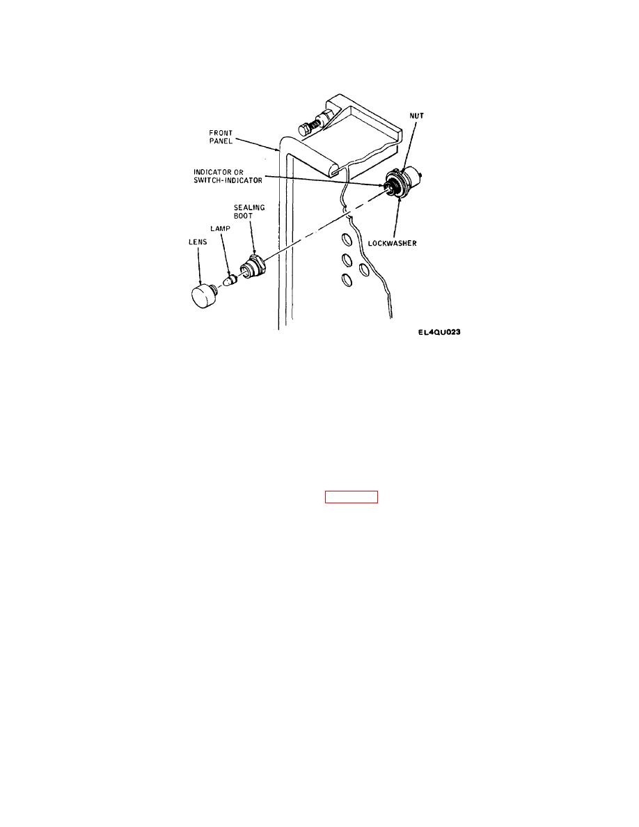
Figure 3-7. Indicator and Switch-Indicator Removal and Replacement |
|
||
| ||||||||||
|
|
 TM 11-7010-201-40-1/ET821-AA-MMI-010/E154 MTS/TO 31S5-2TSQ73-2-1
Figure 3-7. Indicator and Switch-Indicator Removal and Replacement
(4) Replace lens and lamp and secure finger-tight.
(5) Solder tagged wires to new indicator or switch-indicator and remove tags.
(6) Secure front panel to frame following procedure of paragraph 3-12.
3-14. Cable Assemblies W552, W553, and W554 Removal and Replacement. Perform the following procedure to
remove and replace cable assemblies W552, W553, or W554 (figure 3-8).
a. Removal. Remove cable assembly as follows:
(1) Extend MTS from case following procedure of paragraph 3-11.
(2) Remove two screws securing each cable support to right-hand digital card rack (bay 2) and analog card rack
(bay 3).
(3) Remove cable supports from card racks.
(4) Press retainer detent and slide card retainers to one side.
(5) Using card extractor, carefully remove cable assembly printed wiring boards from card racks.
(6) Remove cable assembly from MTS.
3-21
|
|
Privacy Statement - Press Release - Copyright Information. - Contact Us |
