 |
|||
|
|
|||
|
|
|||
| ||||||||||
|
|
 TM 11-6625-667-12/NAVAlR 16-30APM-123-1/TO 33A1-3-367-1
(2) Direct coupling to the transponder set by an
TEST . . . . . . . . . . . . . . . . . . . . . . . .6.5 usec 0.2.
RF cable and attenuator.
4 . . . . . . . . . . . . .Modulation from external
unit
(3) Direct coupling of the test set to Antenna
Side lobe suppression
AT-884/APX-44 by an antenna test hood, a fixed
pulse spacing (Pl
attenuator, and an RF cable.
and P2) . . . . . . . . . . . . . . . . .2.0 usec 0.15.
c. Modes 1,2, 3/A, C, TEST, or 4 can be selected, and
Receiver:
codes 0000 to 7777 can be selected. The TEST mode is
Frequency . . . . . . . . . . . . . . . . . . . 1.090 MHz 0.5%(center).
Bandwidth (3 deci-
used in conjunction with the corresponding trans-
bels down) . . . . . . . . . . . . . . 6.5 MHz l.0.
ponder set mode to allow testing when local
Sensitivity . . . . . . . . . . . . . . . .-9 dbm.
identification transmissions may interfere with the
Gating . . . . . . . . . . . . . . . . . . .Only for duration of
use of the normal modes.
replies.
d. Emergency or identity operation checks can be
Decoding . . . . . . . . . . . . . . . . .Codes 0000 to 7777 includ-
ing emergency and
selected and a three-pulse sidelobe suppression test
identity.
can be selected in all modes, except 4.
Power requirements:
e. A test set self-test can be performed, as a
Type . . . . . . . . . . . . . . . . . . . ..ac or dc
confidence level check, in all modes, except 4.
Ac. . . . . . . . . . . . . . . . . . . . . . .115 volts 10%, 50 through
f. Mode 4 tests may be performed by direct
420 Hz at 0.5 ampere.
Dc. . . . . . . . . . . . . . . . . . . .28 3 volts at 1.5 ampere.
coupling of the test set to an auxiliary interrogator
computer or by direct coupling with an RF cable and
attenuator.
1-6. Differences in Models
Official nomenclature, AN/APM-123(V), followed by
1-5. Technical Characteristics
the number 1, 2, or 3 identifies the type of power
cables supplied with the AN/APM-123(V) for use by
Frequency . . . . . . . . . . . . . . . .1,030 MHz 0.02% crystal
the Army, Navy, or Air Force. Number 1 designates
controlled.
that the components of the test set include power
Power output . . . . . . . . . . . . .-- 6 dbm at antenna terminal.
cables that can only be used by the Army. Number 2
Sidelobe suppression
type . . . . . . . . . . . . . . . . . . . 3 pulse.
designates that the components of the test set
Pulse repetition
include power cables that can only be used by the
frequency . . . . . . . . . . . . . 230 +5 - 10 pps
Navy. Number 3 designates that the components of
Pulse output group . . . . . . . 2 (P1 and P3) without side-
the test set include power cables that can only be
lobe suppression or) (P1,
used by the Air Force. Power cable connections for
P2, and P3) with sidelobe
suppression.
the AN/APM-123(V)l, AN/APM-123(V)2, and AN/
Pulse spacing (P1
APM-123(V)3 are given in paragraph 2-4. Except for
and P3):
the difference in power cables and test hood, the
Mode l. . . . . . . . . . . . . .3 usec 0.2.
components of the AN/APM-123(V)1, AN/APM-
Mode 2 . . . . . . . . . . . . . . .5usec 0.2.
123(V)2, and AN/APM-123(V)3 are mechanically and
Mode 3/A . . . . . . . . . . . . .8 usec 0.2.
Mode C. . . . . . . . . . . . . .21 usec 0.2.
electrically identical.
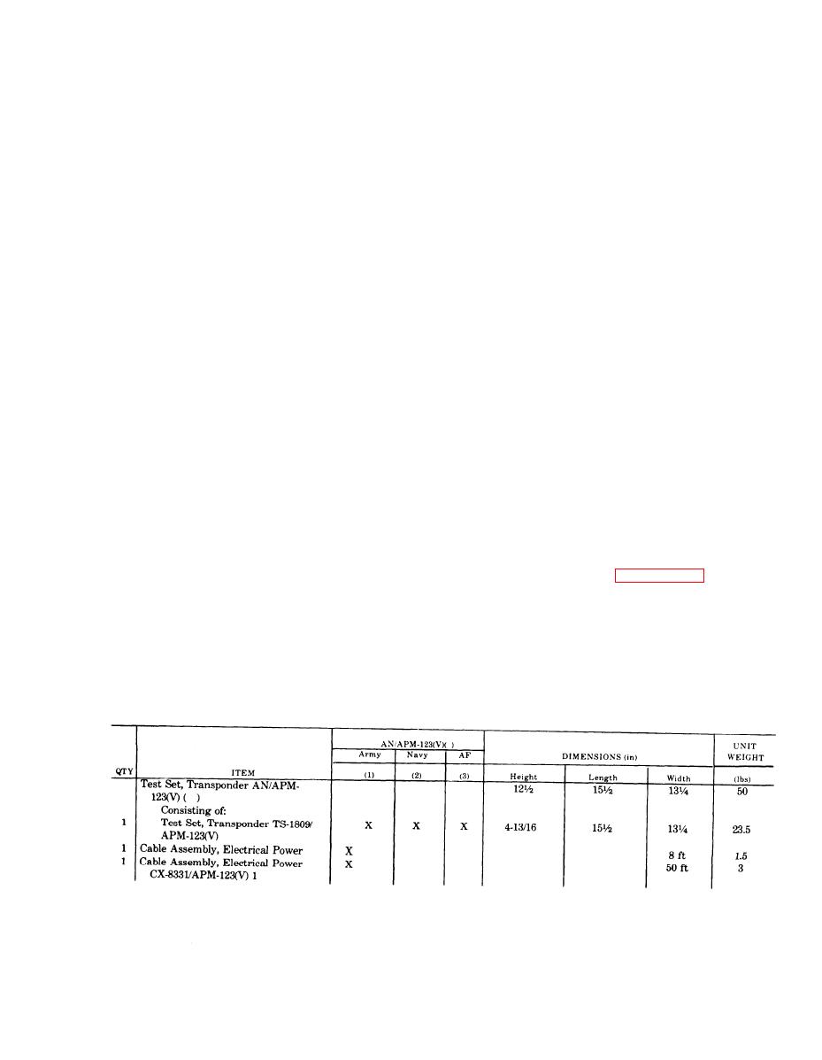
1-7. Items Comprising an Operable AN/APM-123(V)1, 2, or 3
Change 3 1-2.1
|
|
Privacy Statement - Press Release - Copyright Information. - Contact Us |
