 |
|||
|
|
|||
|
Page Title:
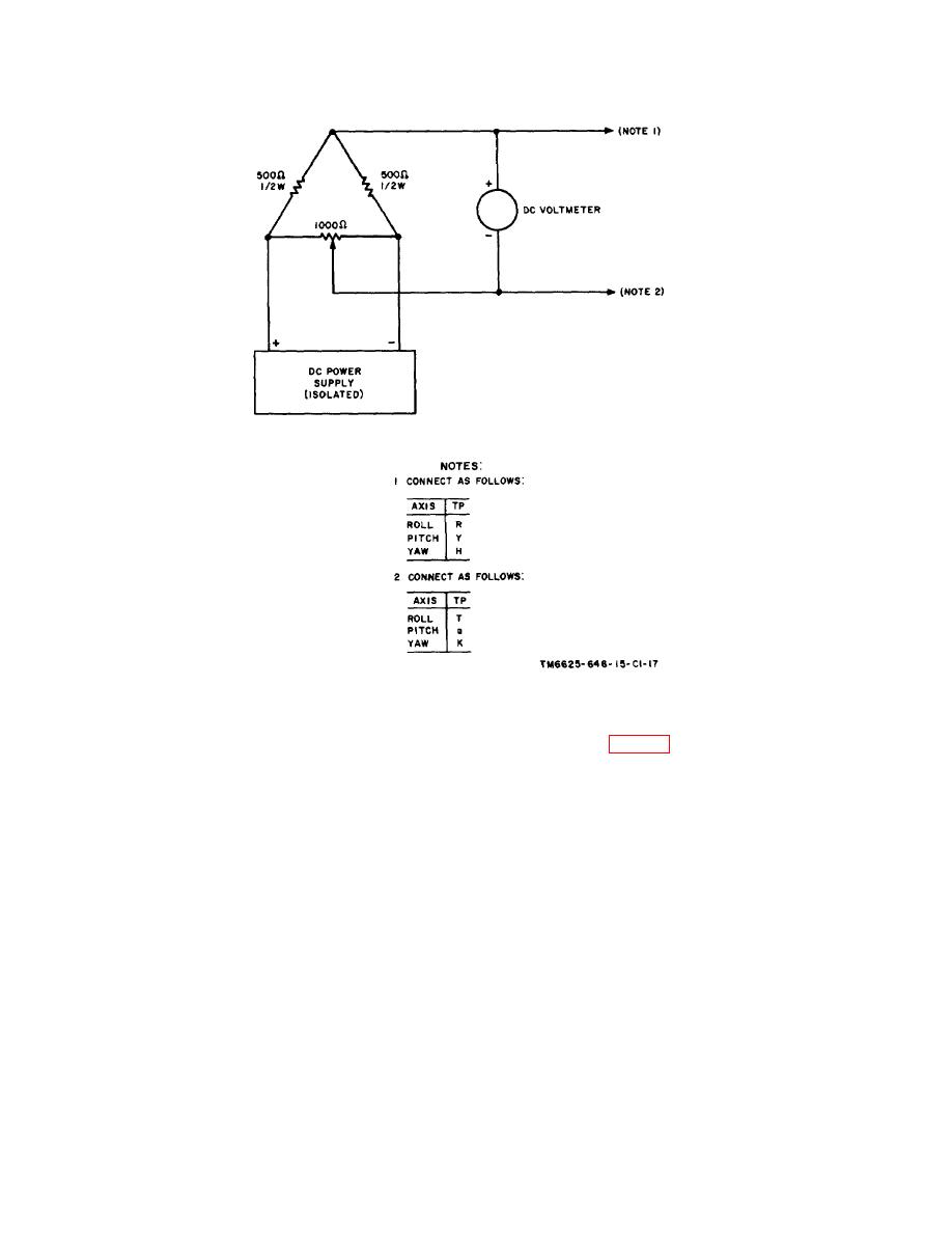
Figure 7-1. Test device, simulated torque motor voltages. |
|
||
| ||||||||||
|
|
 TM 11-6625-646-15
Figure 7-1. Test device, simulated torque motor voltages.
until the dc voltmeter indicates +5. The ROLL AXIS
resistor R609 (fig. 6-7) on the roll actuator simulator
meter should indicate between +4.5 and +5.5 volts.
card for 0 on the meter.
(7) Adjust the test setup variable resistor until
(11) Adjust the test setup variable resistor until
the dc voltmeter indicates 0.
the dc voltmeter indicates 0.1 volt. The ROLL AXIS
meter should indicate a minimum of +1 volt. The vtvm
(8) Adjust the ac supply for a 2.5-volt output.
should indicate a minimum of +1 volt.
(9) Set the AXES METERS READ switch to
(12) Adjust the test setup variable resistor until
CLOSED LOOP.
the dc voltmeter indicates 0.
(13) Reverse the test setup connections at
NOTE
TEST POINTS R and T.
The ROLL AXIS meter may indicate
(14) Adjust the test setup variable resistor until
off scale (hardover).
Allow 30
the dc voltmeter indicates 0.1 volt. The ROLL AXIS
seconds for the circuits to stabilize.
meter should indicate a minimum of -1 volt. The vtvm
should indicate a minimum of 1 volt.
(10) Check that the ROLL AXIS meter
indicates 0 1 scale division. If it does not, adjust
68
|
|
Privacy Statement - Press Release - Copyright Information. - Contact Us |
