 |
|||
|
|
|||
|
Page Title:
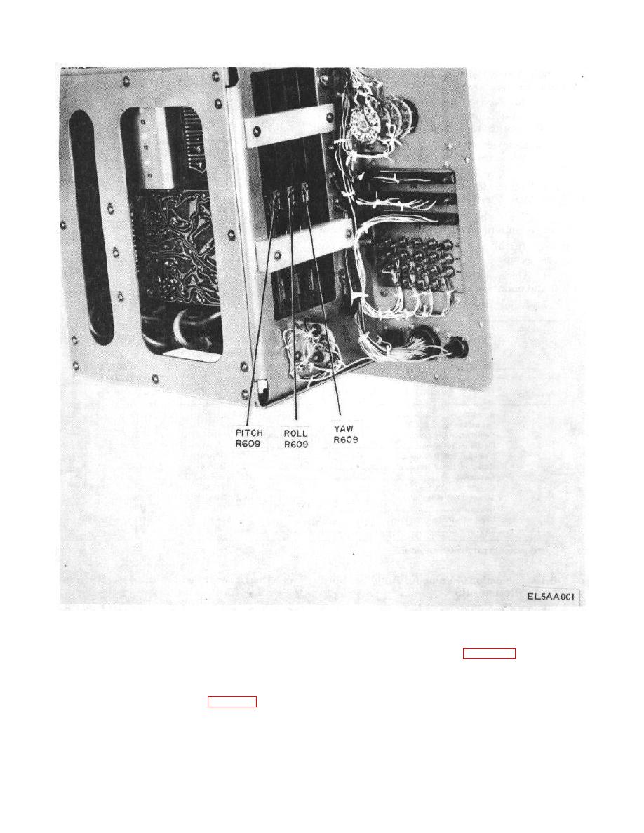
Figure 6-7. Balance resistors location. |
|
||
| ||||||||||
|
|
 TM 11-6625-646-15
Figure 6-7. Balance resistors location.
component, other than those in the demodulator and
the test setup as shown in figure 6-6. Calibrate the filter
output emitter follower circuits, is replaced, the filter and
and meter rectifier circuits as follows:
meter rectifier circuits must be calibrated to determine if
a. Disconnect capacitor C607 and resistor R648
capacitor C607 or resistor R648 must be a different
from the actuator simulator card.
value. Using the material listed in table 6-5, fabricate
b. Install the actuator simulator card in
Change 4 59
|
|
Privacy Statement - Press Release - Copyright Information. - Contact Us |
