 |
|||
|
|
|||
|
Page Title:
Table 6-3. Miscellaneous Test Circuit Troubleshooting |
|
||
| ||||||||||
|
|
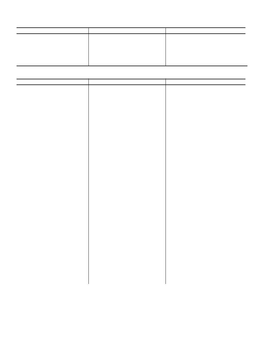 C1, TM 11-6625-646-15
Trouble
Probable cause
Remedy
not present check for 26 vac
between terminals 3 and 5 of
transformer T501. Replace the
transformer or troubleshoot the
115-volt or 26-volt power wiring
as required.
Table 6-3. Miscellaneous Test Circuit Troubleshooting
Trouble
Probable cause
Remedy
115V 400~ POWER indicator
Defective lamp DS1 or circuit
Check the lamp and replace if
lamp does not come on when
breaker switch S1.
defective. If the lamp is good,
switch S1 is operated to the on
check for 115 volts ac at terminal
position.
1 and at terminal 2 of switch
S1; if the voltage is normal at
terminal 1 but not present at
terminal 2, replace the switch.
Defective wiring or broken connec-
If the voltage is not present at
tion at connector J62 or open
contact 1 of S1, check the voltage
circuit in power cable A02VS309-
at the power source; if the
3.
source voltage is normal, check
continuity through connector
J62 and power cable A02VS309-
3; repair as required.
No 26 volts ac between DEM/
Defective wiring or connection
Check for 26 volts ac at terminal
MOD CARD TESTER recep-
between transformer T501 and
3 of power transformer T501. If
tacle J70 pins 18 and 12.
J70-18.
the voltage is normal, trouble-
shoot the circuit between the
transformer and J70-18. Repair
wiring as required.
No 27 volts dc between MAIN
Open circuit between the internal
Check for 27 volts dc at J66 pin 9.
CONNECTOR TEST POINTS
dc power supply and TEST
If voltage is present, troubleshoot
A(+) and C(-).
POINT A.
the circuit from J66 pin 9 to
TEST POINT A. Repair wiring
as required.
Defective resistor R204 or broken
If voltage is not present at J66 pin
connection.
9, check for approximately 32
volts dc at J66 pin 8. If voltage
is present, check resistor R204
and connector wiring. Repair
wiring or replace resistor R204
as required.
DC voltage between MAIN CON-
Defective Zener diode CR501
Replace the diode.
NECTOR TEST POINTS
A(+) and C (-) exceeds 28.5
volts.
DC voltage between MAIN CON-
Defective internal power supply
Replace card A02V3060. If this
NECTOR TEST POINTS
component.
does not correct the trouble,
A(+) and C(-) less than
reinstall the original card and
25.5 volts.
troubleshoot the wiring to J66.
Repair wiring as required.
No 32 volts dc 4 indicated on
Defective switch S3 or associated
Check for approximately 32 volts
external multimeter connected
wiring.
dc at pin 8 of J66. If dc voltage
50
|
|
Privacy Statement - Press Release - Copyright Information. - Contact Us |
