 |
|||
|
|
|||
|
|
|||
| ||||||||||
|
|
 C1, TM 11-6625-646-15
LOOP. Check that the ASE MODE switch is at OFF.
i. If no further tests are to be performed, stop the
Check that the PEDAL POT variable resistor is in the
test set (para 4-20).
center of its operating range (straight up).
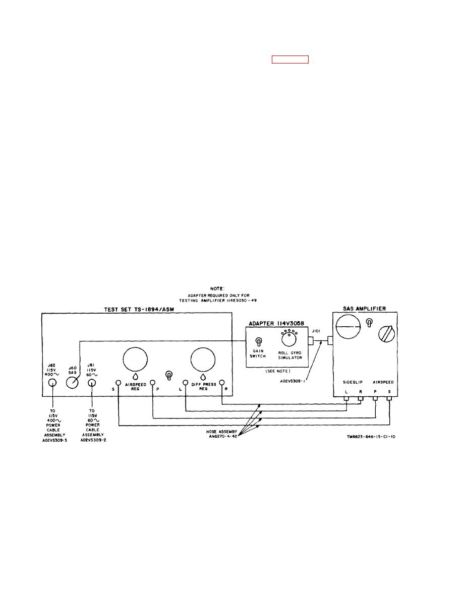
b. Connect the test set S, P, L, and R connections
4-10. ASE Mode Tests
to the corresponding SAS amplifier connections. Use
Not applicable to CH-47 SAS amplifiers.
the hose assemblies and quick-disconnect couplings
furnished with the test set. Connect power cable
4-11. Excitation Voltage Tests
A02VS309-2 between the test set 115V 60~ and a 115-
To check the excitation voltage levels for the link
volt 60-cycle ac source.
feedback component, turn the FUNCTION switch to
c. Set; the PUMP switch to on (up) position.
each POT EXCITATION position. Observe that the
d. Adjust the DIFF PRESS REG valve until the
FUNCTION meter indicates in the green at each
position.
required direction and magnitude of simulated sideslip is
indicated on the SIDESLIP indicator.
4-12. Interlock Voltage Test
e. Observe the output of the sideslip circuit on the
To measure the SAS amplifier half-gain interlock
YAW AXIS meter.
voltage, turn the FUNCTION switch to INTLK. Observe
f. Adjust the AIRSPEED valve until the test
that the FUNCTION meter indicates in the green.
airspeed is indicated on the AIRSPEED indicator.
g. Observe that the YAW AXIS meter indication is
4-13. Pedal Position Variable Resistor Feedback
reduced as required by operation of the airspeed
Voltage Test
circuits.
Not applicable to CH-47 SAS amplifiers.
h. Set the PUMP switch to off (down) position.
Disconnect the hose assemblies from the S, P, L, and R
4-14. Internal Test Circuits
connections. Stow the hose assemblies in the test set
To check the SAS amplifier test circuits, proceed as
cover.
follows:
Figure 4-2. Test setup.
32
|
|
Privacy Statement - Press Release - Copyright Information. - Contact Us |
