 |
|||
|
|
|||
|
Page Title:
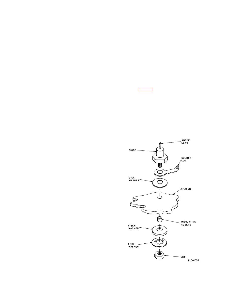
Removal and Replacement of Stud-Type Diodes |
|
||
| ||||||||||
|
|
 TM 11-6625-467-34
removed from the board and replaced with another
polyethylene container and stir with a stainless
part, the following procedure should be followed.
steel spatula or equivalent. Mix thoroughly.
The bonding agent used in recoating the boards is a
i. Apply the mixture to the newly soldered joint;
postcoating material, Dennis 1169. This material
c o v e r all areas where the original coating was
consists of two parts, Dennis 1169A and 1169B. The
damaged and any new parts which were added. Use
two parts must be mixed at the time of use.
a soft-bristled brush to apply the mixture.
a. I n s p e c t t h e c a r d f o r e v i d e n c e o f b u r n s ,
j. Allow the newly coated cards to dry to a
scorches, or heat damage; corroded metal parts or
tackfree condition (approx. 2 hours) before install-
terminals, or damage of the base laminate. If any of
ing them in the equipment. The final cure takes ap-
these defects are evident, replace the entire board
proximately 7 days at room temperature or 1 hour
rather than attempting repair. If the board appears
at +60 C. (+140F.); however, the equipment may
repairable, proceed to b below.
be operated during the curing period.
b. Remove the designated part from the card by
3-11. Removal and Replacement of
destroying the protective postcoating with a hot
Stud-Type Diodes
soldering iron, and then unsolder the part and lift it
off the board with a pair of long-nosed pliers.
The stud-type diodes in the test set must be elec-
CAUTION
trically insulated from the chassis to which they are
Do not use soldering irons rated above 25
mounted. Follow the procedures in a and b b e l o w
watts on cards bearing transistors, cerafil
when removing or replacing this type diode.
capacitors, or other heat sensitive com-
a. Removal.
ponents. Also, be very careful when re-
(1) Unsolder the wire or wires connected to the
moving components from the card so that
anode lead of the diode.
the circuits are not damaged.
(2) Remove the nut from the bottom of the
c. If necessary, remove the excess solder from
chassis.
the joint with a soldering iron.
d. Insert the new wire or component lead in the
correct eyelet and clinch the wire over the eyelet.
core solder. Do not use a solder that has a core of
hydrazine, acid, or other unapproved flux. Do not
keep the iron on the joint longer than necessary to
complete the solder flow throughout the joint.
f. Inspect the solder joint to be sure the solder
completely covers the joint and there is a smooth
continuous band of solder between the eyelet flares
and the circuitry. Note also that there are no cold or
fractured solder joints or nonadherence of solder to
metal and no excess solder globules, peaks, strings,
o r bridges of solder between adjacent parts or
circuits.
g . Clean the joint to remove the flux; use a
m e d i u m - b r i s t l e d brush and a small amount of
organic solvent. Remove as much of the melted plas-
tic and flux from the soldered area as possible.
Remove excess solvent and dissolved flux with an
absorbent material.
NOTE
Use a solvent sparingly since the
postcoating will also be dissolved. Apply a
small amount to the area of the solder joint
only.
h. Mix one part of Dennis 1169A liquid with one
part Dennis 1169B liquid. Mix these two liquids
together in a stainless steel, wax free paper, or
Figure 9-26. Insulated mounting of stud-type diodes.
3-39
|
|
Privacy Statement - Press Release - Copyright Information. - Contact Us |
