 |
|||
|
|
|||
|
Page Title:
Power Supply Circuits |
|
||
| ||||||||||
|
|
 TM 11-6625-467-34
hertz range are therefore identical. Switch S7
is more complex, the switches provide a basic func-
selects one of the two codes by generating an am-
tion similar to S1 in the simple switching arrange-
biguity code. For the 30-megahertz range, switch
ment of figure 2-30. The test set switching circuits
S7A, section Z grounds megahertz ambiguity line A.
are described in b and c below.
Megahertz ambiguity line B is grounded when S7 is
b. 0.05 Megahertz Switching. Switch S9 selects
set to 50. The same general concept is true for posi-
fractional megahertz in steps of 0.05 megahertz.
tions 40 and 60 of switch S7. Switch S7 connects the
five lines from S8A and S8C to the megahertz select
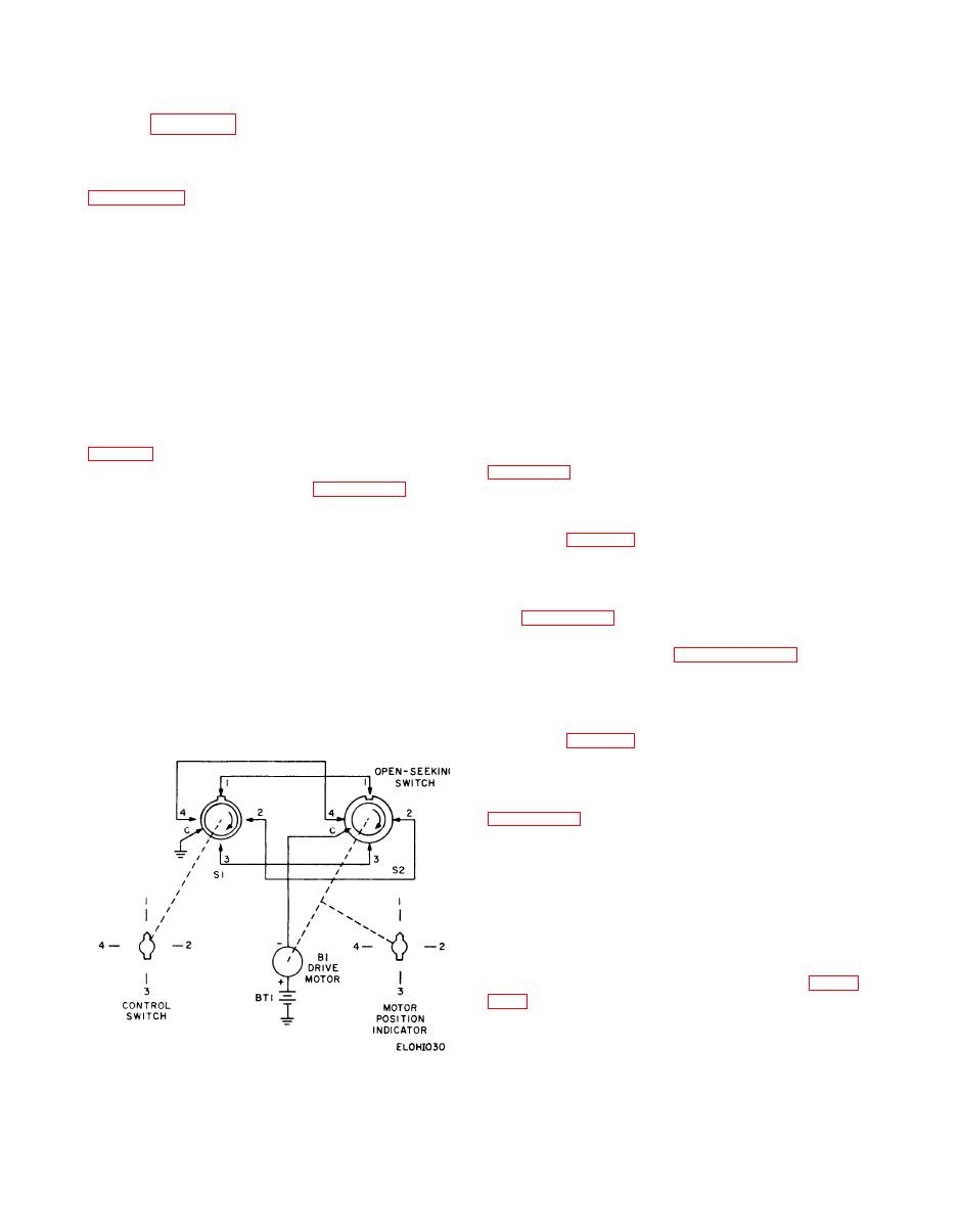
switch connected to a typical drive circuit. Switch
lines A through E. Megahertz ambiguity line A is
S9 is shown in the .00 position with megahertz select
grounded in the 40 position, and megahertz ambigui-
lines A and E grounded by S9 rear. Drive motor B1
ty line B is grounded in the 60 position, distinguish-
has positioned S1 so that megahertz select A and E
i n g the two frequency ranges. Switch S8 also
lines are disconnected from the driver motor. When
generates an odd-even megahertz code for the low
S9 is set to the .05 position, S9 rear grounds the
frequency oscillator in the AN/ARC-54 RF sub-
megahertz select B line only. A ground path from
chassis. Switch S8E grounds the even megahertz
the megahertz select B line, through contact 3 on S1
cycle ground line on all even megahertz switch set-
front, energizes the motor. The motor turns S1 in
tings (that is, O, 2,4,6, . . . and so forth) and grounds
the direction shown by the arrows. When the switch
segment leaves contact 3 on S1 front, the ground cir-
the odd megahertz ground line on all odd megahertz
cuit to the motor is opened and the motor stops. The
settings. The combination of switches S7 and S8
tune the RF subchassis to any whole megahertz fre-
same action occurs for other positions of the switch.
quency in the 30- to 70-megahertz frequency range.
hertz selector switch.
megahertz setting.
the complete test set tuning circuit. Switches S7 and
2-36. Power Supply Circuits
S8 perform the whole-megahertz tuning. Switch S8
generates three sets of codes. One code covers the
The test set contains a positive 27.5-volt regulated
30- to 39- and the 50- to 59-megahertz ranges;
power supply, a negative 27.5-volt regulated power
another code covers the 40- to 49- and 60- to 69-
supply, and a positive 500-volt regulated power sup-
megahertz ranges; a third code discriminates be-
ply. Figure FO-2 is a simplified schematic diagram
tween odd and even megahertz by placing alternate
showing the power supplies and associated switch-
grounds on the odd-even megahertz lines. Switch
ing and metering circuits. Paragraphs 2-37 through
S8B and S8D form another five-wire code generator
2-43 describe the power supplies and associated
for the 40- and 60-megahertz ranges. In positions 30
and 50, switch S7 connects the five lines A through
circuits.
E. The codes for frequencies in the 30- and 50-mega-
2-37. Primary Power Circuit
The primary power circuit for the test set may be
connected for either 115-volt operation or 230-volt
operation by changing the connection of plug P1.
jack J30 connect the primary windings of trans-
former T1 in parallel. Under this condition, the unit
operates from a 115-volt power source. For 230-volt
operation, plug P1 connects to J31. In this case, the
primary windings are connected in series. Interlock
switch S12 disconnects power from transformer T1
when the unit is taken out of the case. Taps on the
primary of transformer T1 are connected to ter-
minal board TB1. The connection shown in figure
low line voltage conditions exist, wires from pins A
and B of plug PI are connected to terminals 3 and 4,
respectively, on terminal board TB1. Using these
connections, the equipment operates from a 105-volt
Figure 2-30. Four-wire reentrant tuning system, simplified
schematic diagram.
or a 210-volt power source, depending on the place-
2-73
|
|
Privacy Statement - Press Release - Copyright Information. - Contact Us |
