 |
|||
|
|
|||
|
Page Title:
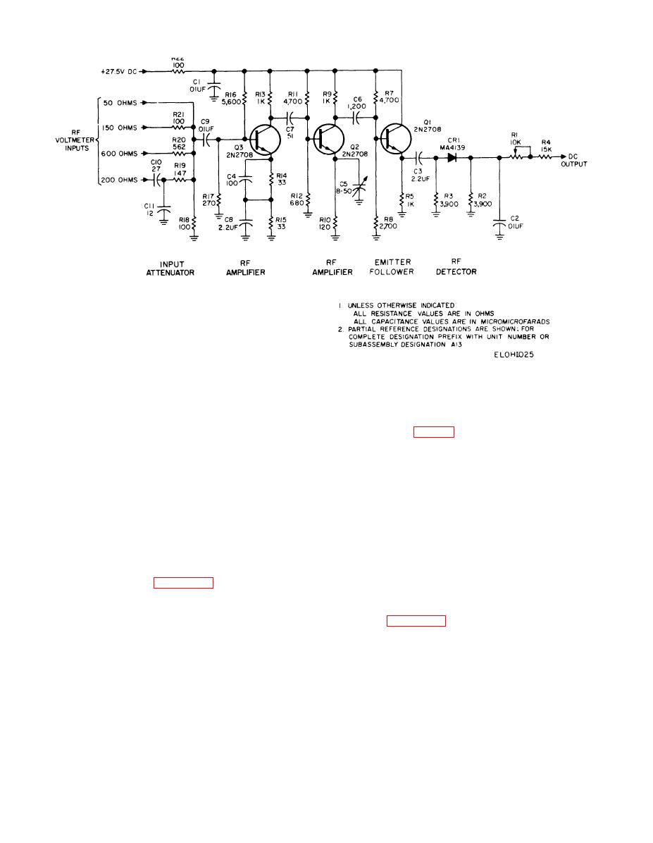
Figure 2-25. RF amplifier/detector circuit, simplified schematic diagram. |
|
||
| ||||||||||
|
|
 TM 11-6625-467-34
Figure 2-25. RF amplifier/detector circuit, simplified schematic diagram.
the narrow band mode is used to adjust the 500-kHz
kHz 700 Hz (B, fig. 2-26). If the frequency is within
oscillator frequency. The circuit operation for each
the pass band of the filter, the resulting meter read-
mode is discussed below.
ing will be greater than one-half of the meter read-
ing obtained during calibration.
a. Wide Band Operation. The 500 KC FILTER
control adjusts the amplitude of the 500-kHz input.
NOTE
Capacitor Cl couples the input signal to the base of
Amplifier Q1 compensates for losses in the
transistor Q1. The amplifier circuit of transistor Q1
filters. If the frequency falls outside the
amplifies the 500-kHz signal and applies it to 500-
pass band, a meter reading of less than half
kHz bandpass filter FL2. Filter FL2 is a mechanical
the calibration reading will be obtained.
bandpass filter with a center frequency of 500-kHz
and a pass band of 700 Hz at the --6-db points. A
b. Narrow Band Operation. The circuit operation
graphical representation of the pass band of filter
for the narrow band or crystal mode is essentially
FL2 is shown in B, figure 2-26. Capacitors C4, C5,
the same as for wide band operation except that a
crystal filter is added to the circuit. A graphical
C9, and C10 tune the center frequency of the filter
to exactly 500 kHz. The Q2 emitter follower circuit
representation of the crystal filter pass band is
provides a high impedance input circuit for the filter
given in C, figure 2-26. Notice that the pass band of
output. Resistor R32 is a circuit calibration control
the crystal filter is much narrower than that of the
mechanical filter. The narrow band mode of opera-
that adjusts the circuit output level for a given in-
put. In using the circuit for making go-no-go fre-
tion is used to adjust the oscillator in the transmit
quency checks of a 500-kHz signal, first the 500-kHz
audio module to 500 kHz Y100 Hz. In the narrow
input signal at the movable arm of R6 is connected
band operation, the 500-kHz oscillator output con-
nects to 500 KC FILTER potentiometer R6, which is
to the metering circuit and R6 is adjusted for a
specified calibration point on the TEST METER.
set for a convenient TEST METER indication. The
metering circuit is connected to the crystal filter
Second, the meter is connected to the 500-kHz band-
pass filter output. The response of the bandpass
output and the 500-kHz oscillator frequency is ad-
filter is essentially flat in the frequency range of 500
justed for a peak TEST METER reading.
2-66
|
|
Privacy Statement - Press Release - Copyright Information. - Contact Us |
