 |
|||
|
|
|||
|
Page Title:
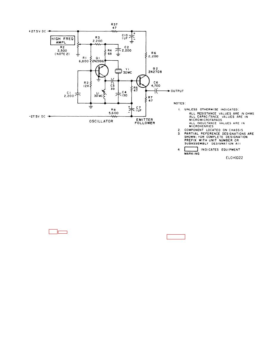
Figure 2-22.30 MHz oscillator circuit, simplied schematic diagram. |
|
||
| ||||||||||
|
|
 TM 11-6625-467-34
Figure 2-22.30 MHz oscillator circuit, simplied schematic diagram.
represents 100-percent distortion. After this cali-
emitter has zero phase shift, thus sustaining circuit
oscillation. HIGH FREQ AMPL control R2 varies
bration is made, the high pass filter output (dis-
the dc level at the emitter of Q1. This voltage con-
tortion detector output) is connected to the meter
trols the oscillator output level. Transistor Q2 is the
circuit. The high pass filter removes the 1-kHz fun-
output emitter follower circuit. The circuit trans-
damental frequency and leaves only the harmonic
forms the high oscillator output impedance to a low-
components of the signal present at the distortion
output impedance. The emitter follower circuit also
output. The meter indicates the voltage value of the
harmonic components present at the distortion out-
prevents the external circuits from loading the
crystal oscillator.
put, thereby giving an indication of the harmonic
distortion of the input signal.
2-28. Distortion Detector
2-29. Audio Amplifier/Detector
The distortion detector measures the harmonic dis-
.
The audio amplifier/detector circuit in conjunction
tortion of a 1 kHz signal. The circuit is composed of
with the TEST METER performs as an electronic
transistor amplifier Q6, 2-kHz high pass filter FL1,
voltmeter in the test set. The CIRCUIT SELECTOR
and associated components. The distorted 1-kHz sig-
switches connect various oscillator and module cir-
nal is applied to the distortion detector input. DIST
DET control R4 adjusts the signal input level.
cuit outputs in the frequency range of 150-Hz to
500-kHz to the audio amplifier/detector input. The
Capacitor C19 couples the input signal from R4 to
circuit amplifies and rectifies signals and applies the
the base of transistor Q6. The amplifier circuit of
resulting dc voltage to the meter circuit. Capacitor
transistor Q6 amplifies the signal and applies it to
filter FL1 and to a voltage divider consisting of R35
C15 couples the input signal to the base of transistor
Q1. The emitter follower circuit of Q1, current ampli-
and R36. Both the voltage divider output and the
fies the signal and applies it to the base of Q2
high pass filter output connect to the meter circuit
through coupling capacitor C16. The amplifier cir-
through switches. In the use of the distortion detec-
cuit of transistor Q2 amplifies the signal and applies
tor, first the meter circuit is switched to the voltage
it to the base of transistor Q3 through C19 and sen-
divider output and DIST DET control R4 is adjusted
for a predetermined meter reading. This reading
sitivity control R11. Resistor R11 controls the signal
2-63
1
|
|
Privacy Statement - Press Release - Copyright Information. - Contact Us |
