 |
|||
|
|
|||
|
Page Title:
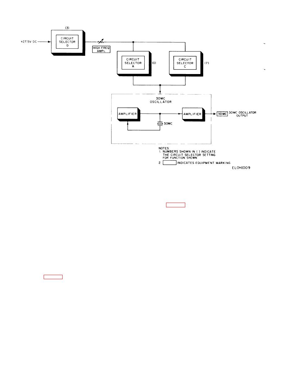
Figure 2-9. 30 MHz oscillator circuit, functional diagram. |
|
||
| ||||||||||
|
|
 TM 11-6625-467-34
Figure 2-9. 30 MHz oscillator circuit, functional diagram.
CIRCUIT SELECTOR C (position 1). The DIST
to the ac voltmeter circuit.
DET control is adjusted for a specified reading on
2-18. RF Power Detector Signal Paths
t h e TEST METER. This reading represents 100
percent distortion. Next, CIRCUIT SELECTOR C
The test set RF power detector circuit provides a
is switched to position O. The amplifier output must
means to measure the AN/ARC-54 power amplifier
n o w pass through highpass filter FL1 before it
output power. The power amplifier connects to J9
reaches the voltmeter circuit. The highpass filter
only passes frequencies above 1 kHz; therefore,
o n the test set when the AN/ARC-54 RF sub-
the fundamental frequency is filtered out and all
chassis is plugged into J2. Connector J9 applies the
RF power to attenuator AT1 which provides a 50
that remain are the harmonic components gener-
ated as a result of nonlinear amplification in the
ohm load impedance for the power amplifier. The
attenuator also acts as a power divider and applies
module circuit under test. The TEST METER indi-
a portion of the input power to power detector A14.
cates the amplitude of these harmonic components
The power detector rectifies the RF signal and pro-
as a percentage of the original signal amplitude.
duces a dc output voltage that is proportional to the
2-17. 500 kHz Discriminator Signal Paths
RF input voltage. The dc output of the power de-
tector is applied to CIRCUIT SELECTOR B. CIR-
The 500 kHz discriminator demodulates the fm 500
CUIT SELECTOR B (position 0) connects the dc
kilohertz output of the transmit audio module. In
voltage to CIRCUIT SELECTOR A. When CIR-
position 3, CIRCUIT SELECTOR A connects the
CUIT SELECTOR A is in position O, it transfers the
dc voltage to the dc voltmeter circuit for readout.
transmit audio module 500 kilohertz output to the
discriminator input. The discriminator output con-
2-19. Signal Paths (Operating Procedures)
nects to one of two places through CIRCUIT SE-
of CIRCUIT SELECTOR Switches
LECTOR switches. In position 2, CIRCUIT SE-
The test set contains a group of functional circuits
LECTOR B connects the discriminator output to the
such as oscillators, amplifiers, and detectors, con-
distortion detector circuit. CIRCUIT SELECTOR
n e c t e d together by a switching arrangement for
C, in position 2, connects the discriminator output
2-10
|
|
Privacy Statement - Press Release - Copyright Information. - Contact Us |