 |
|||
|
|
|||
|
Page Title:
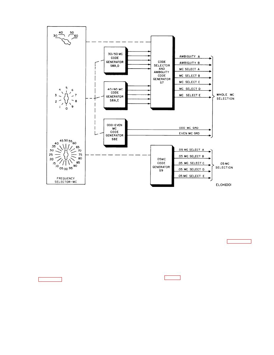
Figure 2-1. Frequency selector switch circuit, functional diagram. |
|
||
| ||||||||||
|
|
 TM 11-6625-467-34
Figure 2-1. Frequency selector switch circuit, functional diagram.
LECTOR B or C connects the RF amplifier/detector
sired voltage. C I R C U I T SELECTOR A selects
output to CIRCUIT SELECTOR A. CIRCUIT SE-
either CIRCUIT SELECTOR B or C and connects
LECTOR A connects either CIRCUIT SELECTOR
the selected output to the audio amplifier/detector
B or C to the PRESS TO TEST switch. The PRESS
input. The audio amplifier/detector amplifies and
TO TEST switch connects the dc voltage to the
detects the ac input voltage and produces a dc out-
TEST METER for readout.
put voltage that is proportional to the input ampli-
c. Dc Voltage Measurements. Dc voltages in the
tude. CIRCUIT SELECTOR A also connects the
test set are measured as shown in C, figure 2-2.
audio amplifier/detector output to the PRESS TO
The dc voltages connect to CIRCUIT SELECTOR C.
TEST switch. The PRESS TO TEST switch con-
CIRCUIT SELECTOR C selects the dc voltage to be
n e c t s the dc voltage to the TEST METER to
m e a s u r e d and applies the voltage to the TEST
readout.
METER through the PRESS TO TEST switch.
(RF) voltages in the test set, within the frequency
2-5. 150 Hz Oscillator/Counter Signal Paths
range of 3 to 70 megahertz, are measured as shown
The 150 Hz oscillator/counter is a single circuit that
front panel connectors RF VM1, RF VM2, RF VM3,
performs two functions as follows:
and RF VM4 by RF jumper cables supplied with the
equipment. The four inputs, RF VM1 through RF
an oscillator by CIRCUIT SELECTOR D (position 1)
VM4, match 50 ohm, 150 ohm, 200 ohm, and 600 ohm
which connects the output of the 150 Hz amplifier to
input impedances, respectively. The RF amplifier/
the circuit input. The 150 CPS AMPL control varies
detector amplifies and detects the RF input voltage
.
the oscillator output level. CIRCUIT SELECTOR B
and produces a dc output voltage that is propor-
(position 4) connects the 150 Hz oscillator to the
tional to the RF input amplitude. CIRCUIT SE-
2-3
|
|
Privacy Statement - Press Release - Copyright Information. - Contact Us |
