 |
|||
|
|
|||
|
|
|||
| ||||||||||
|
|
 TM 11-6625-467-12
(1) Remove the 16 screws that secure the front
(2) Remove the front panel from the cabinet.
panel.
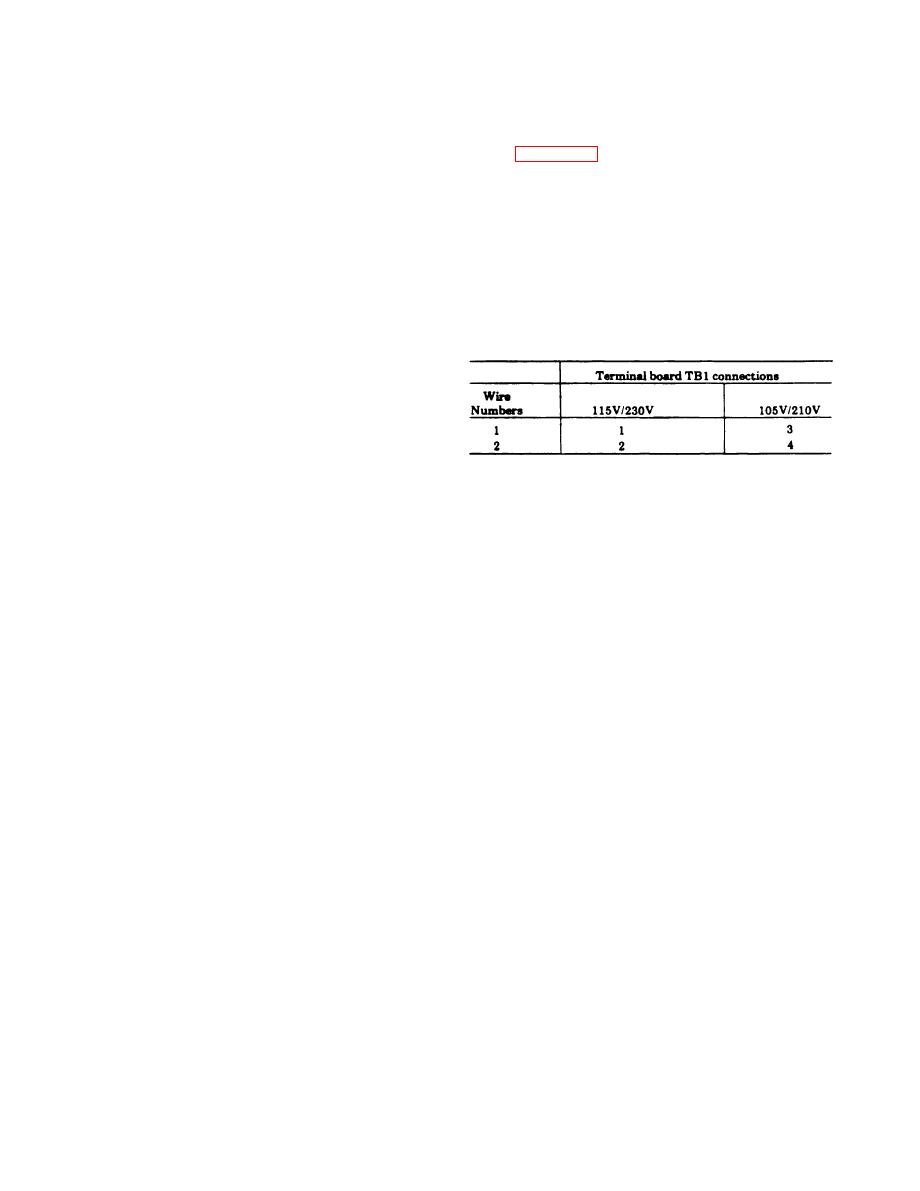
(3) Table 2-2 shows the connections to terminal
board TBl for normal and low line voltages. Con-
CAUTION
nect the wires to correspond to existing line voltage
Remove the panel carefully; the front
conditions.
panel and cabinet are joined by an in-
tercomecting cable.
NOTE
T h e equipment is shipped from the
(2) Remove the front panel from the cabinet.
f a c t o r y set for 115-volt operation;
(3) Connect tinned plug P1 to 230V jack J31 on the
normally the wires will be connected to
rear of the front panel.
terminals land 20f TB1.
(4) Replace the front panel into the cabinet.
(5) Replace the 16 screws.
c. Low Line Voltage Compensation. Perform the
Table 2-2 Low Line Voltage Compensation Connections
following steps to compensate for low line voltage.
(1) Remove the 16 screws that secure the front
panel.
CAUTION
Remove the panel carefully; the front
p a n e l and cabinet are joined by in-
terconnecting cable.
2-4
|
|
Privacy Statement - Press Release - Copyright Information. - Contact Us |
