 |
|||
|
|
|||
|
Page Title:
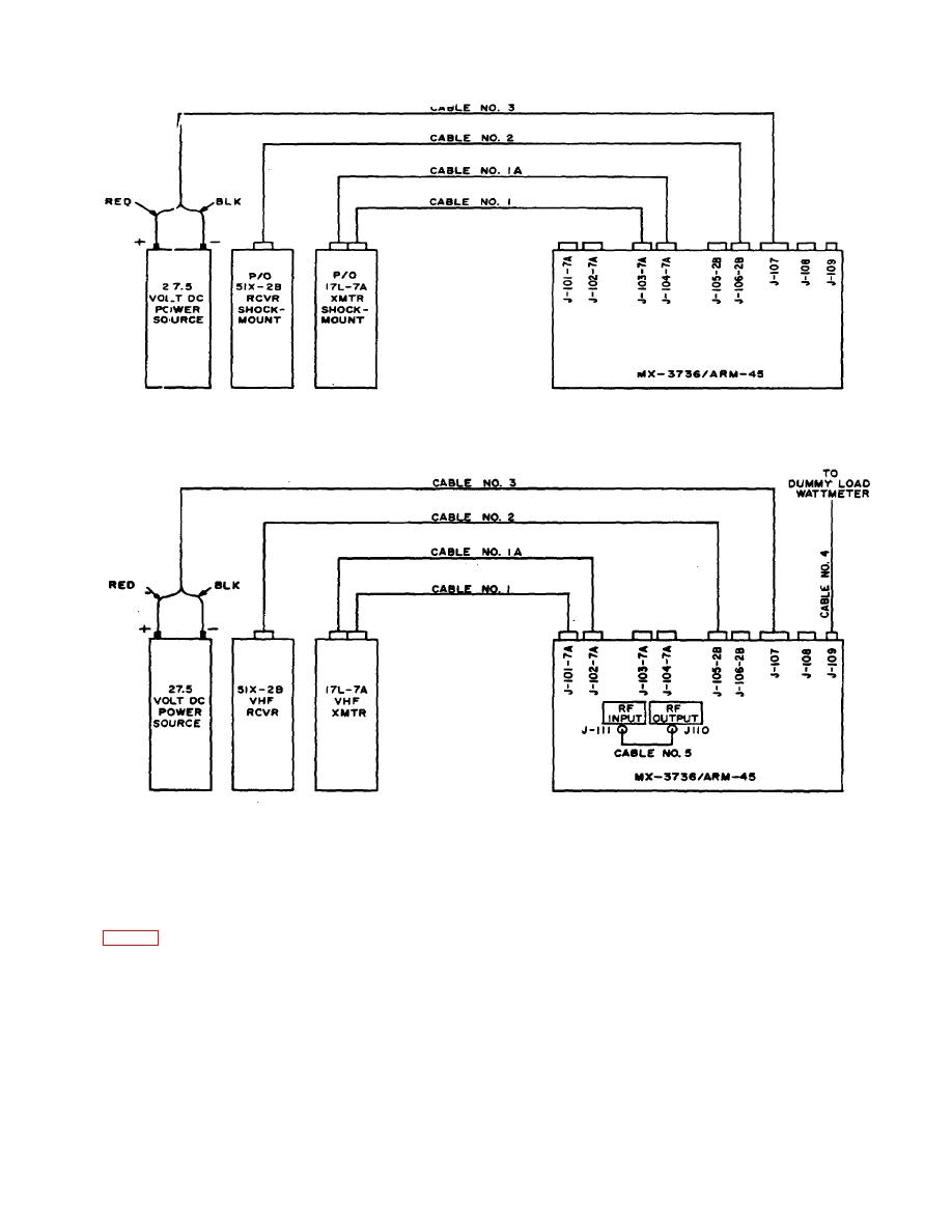
Figure 2-6. Cabling diagrams for typical aircraft and bench tests |
|
||
| ||||||||||
|
|
 TM 11-6625-409-12
A. REMOTE CONTROL UNIT AND WIRING TEST
B. TRANSMITTER AND RECEIVER BENCH TEST
ELOEAOO8
Figure 2-6. Cabling diagrams for typical aircraft and bench tests
using the AN/ARM-45(*) to perform functional tests of
2-9. Testing radio Transmitter and Receiver at
Transmitter 17L-7A and Receiver 51X-2B at the
Maintenance Bench
maintenance bench.
(B, fig. 2-6)
a. Unlatch and remove the case cover on the
The following describes typical procedures
for
2-11
|
|
Privacy Statement - Press Release - Copyright Information. - Contact Us |
