 |
|||
|
|
|||
|
Page Title:
TRANSPORT STATUS (Circuit Card 1A2A1 ) |
|
||
| ||||||||||
|
|
 TM 11-6625-3024-14/EE641-AC-MMA-010/E154 SYSEX/TO 33AA50-5-1-1
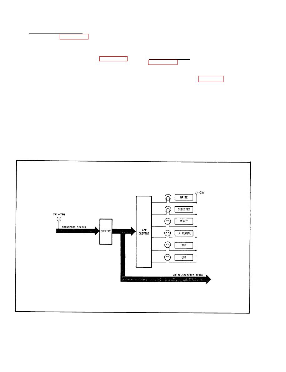
4-8. TRANSPORT STATUS (Circuit Card
following functions: WRITE, SELECTED, READY,
1A2A1 ) (See Figure FO-6)
IN REWIND, BOT (Beginning-Of-Tape), and EOT
(End-Of-Tape).
The status circuit receives status information
from the transport to light status indicators on the
4-9. DATA CONTROL (Circuit Card 1A2A2) (See
front panel of the Exerciser. (See Figure 4-7,
Transport Status Block Diagram.)
The Data Control circuits select the type of data
Transport status lines are received through
to be written on tape. (See Figure 4-8, Data Con-
buffers that convert the transport negative logic to
trol Block Diagram.)
the Exerciser positive logic levels. The outputs of
the buffers are applied to Lamp Drivers that
The Data Select switches are push-ON/
provide a return signal for the enabled status
push-OFF type switches. When a Data Switch is
indicator. The status indicators operate on +28
selected the switch latch is set. The outputs of the
Vdc.
latches are applied through open collector buffers
to lamp drivers. The lamp drivers provide a return
The status lines are also routed to the status
for the 28 Vdc indicator lamps.
selector on the processor circuit card. The
Exerciser indicates transport status for the
Figure 4-7. Transport Status Block Diagram
4-12
|
|
Privacy Statement - Press Release - Copyright Information. - Contact Us |
