 |
|||
|
|
|||
|
Page Title:
Table 3-2. Connector Panel Controls |
|
||
| ||||||||||
|
|
 TM 11-6625-3024-14/EE641-AC-MMA-010/E154 SYSEX/10 33AA50-5-1-1
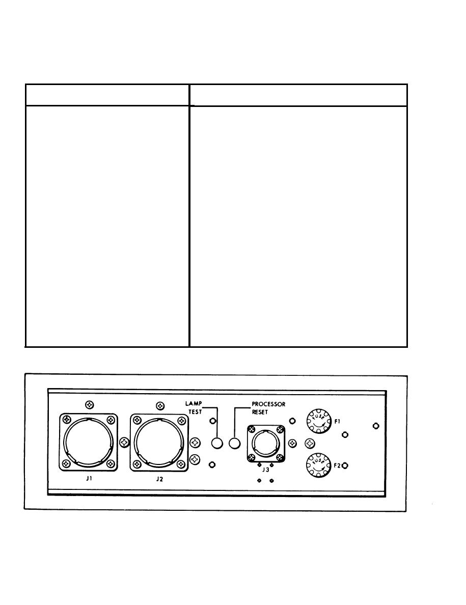
Table 3-2. Connector Panel Controls
Control/Indicator
Function
F1
+ 2 8 Vdc transport power
f u s e . (5 amp
Fuse
SLO-BLOW)
F2
+ 2 8 Vdc Exerciser lamps
f u s e . (3 amp
Fuse
SLO-BLOW)
Note
Fuse F2 does not protect lamps for
transport power switch, system power
switch, and STOP switch.
LAMP TEST
Lights all Exerciser indicator lamps, including the
Switch
PARITY ERROR LED display indicators. The
LAMP TEST switch will not light the Transport and
System Power ON/OFF and the WRITE DATA
indicators.
PROCESSOR RESET
Resets all DATA CONTROL and MOTION
Switch
CONTROL Indicators, except STOP and WRITE
RESET indicators.
Figure 3-2. Connector Panel Controls
3-10
|
|
Privacy Statement - Press Release - Copyright Information. - Contact Us |
