 |
|||
|
|
|||
|
Page Title:
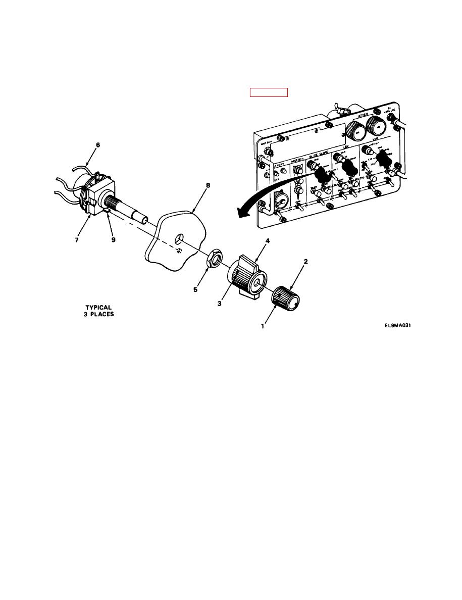
ROTARY SWITCH S7, S11, AND S17 REPLACEMENT. |
|
||
| ||||||||||
|
|
 TM 11-6625-2976-40
2-32. ROTARY SWITCH S7, S11, AND S17 REPLACEMENT.
MATERIALS/PARTS: Switch, rotary for S7 and S11 (PIN SP6325)
Switch, rotary for S17 (P/N 259-8018-020)
PRELIMINARY PROCEDURE: Remove A6 and A8 assembly (para 2-19).
REMOVAL
1. Using hex wrench, loosen two setscrews (1) and remove knob (2).
2. Using hex wrench, loosen two setscrews (3) and remove knob (4).
3. Using wrench, remove retaining nut (5).
4. Using soldering iron, unsolder wires (6) one at a time and resolder to replacement switch.
INSTALLATION
1.
Push switch (7) into front Ianei (8), placing locating pin (9) in hole in rear of front panel.
2.
Install retaining nut (5).
3.
Using wrench, tighten retaining nut (5).
4.
Install knob (4) and, using hex wrench, tighten two setscrews (3).
5.
Install knob (2) and, using hex wrench, tighten two setscrews (1).
2-78
|
|
Privacy Statement - Press Release - Copyright Information. - Contact Us |
