 |
|||
|
|
|||
|
Page Title:
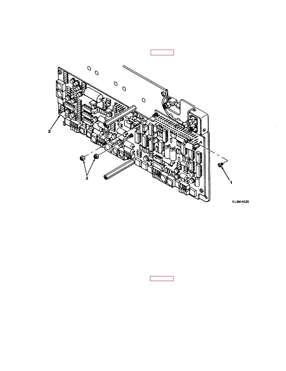
A6 CIRCUIT BOARD ASSEMBLY REPLACEMENT. |
|
||
| ||||||||||
|
|
 TM 11-6625-2976-40
2-20. A6 CIRCUIT BOARD ASSEMBLY REPLACEMENT.
MATERIALS/PARTS: Circuit board assembly, A6 (P/N 629-0206-001)
PRELIMINARY PROCEDURE: Remove A6 and A8 assembly (para 2-19).
REMOVAL
1. Using screwdriver, remove four screws (1).
2. Using socket driver, remove two nuts (2).
3. Carefully pull circuit board (3) straight up to release from pins.
INSTALLATION
1. Position circuit board (3) on pins and push into place.
2. Install two nuts (2) and, using socket driver, tighten.
3. Install four screws (1) and, using screwdriver, tighten.
FOLLOW-ON MAINTENANCE: Install A6 and A8 assembly (para 2-19).
2-64
|
|
Privacy Statement - Press Release - Copyright Information. - Contact Us |
