 |
|||
|
|
|||
|
|
|||
| ||||||||||
|
|
 TM 11-6625-2976-40
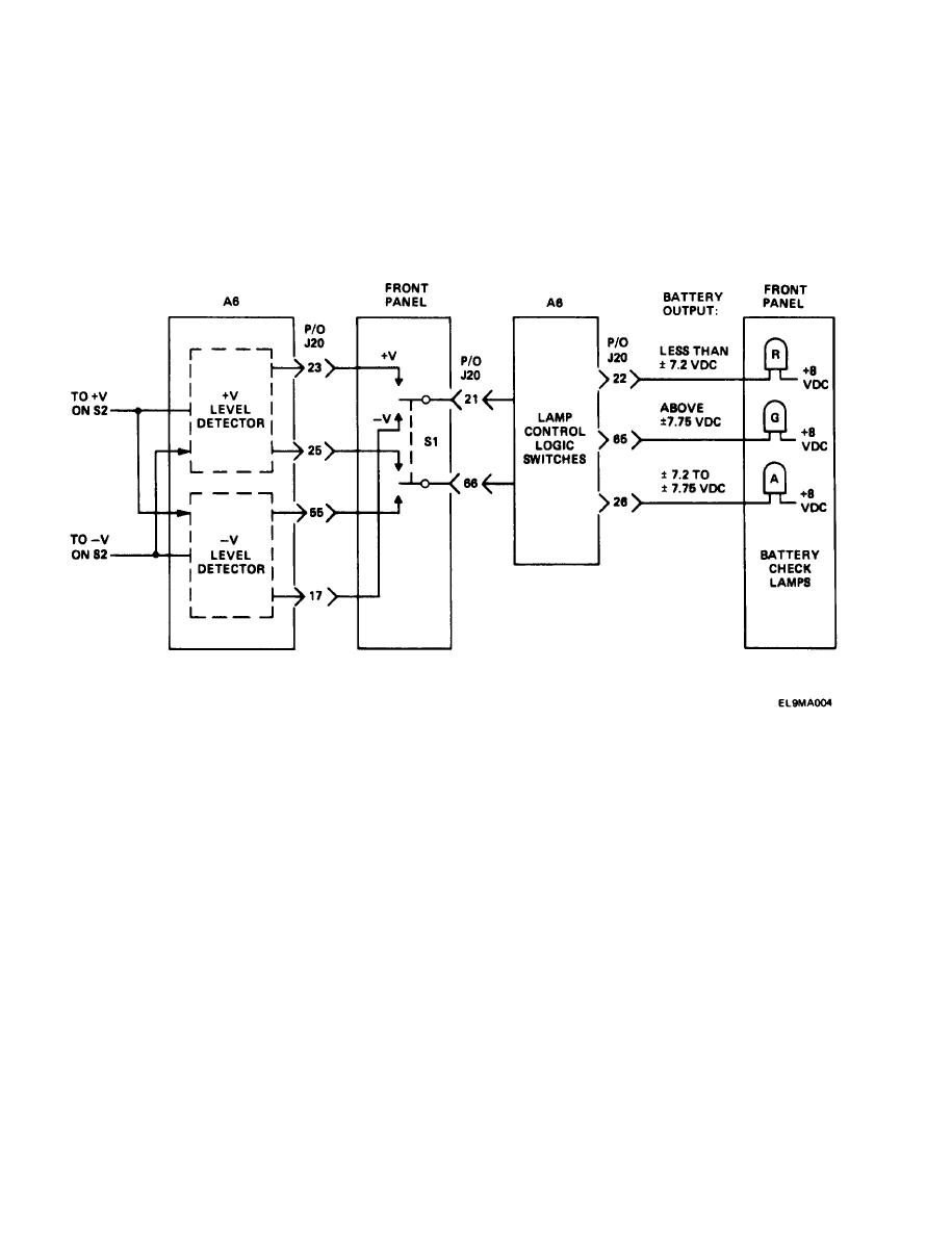
1-15. BATTERY CHECK CAPABILITY.
An Internal voltage check circuit provides an instantaneous test for test set batteries. As a result of this
test, front panel lamps wiII Indicate whether or not batteries need recharging. The battery check is
Independent of other test set functions and maybe initiated at any time, as long as power (PWR)
switch S2 is in ON position.
Positive or negative battery output voltages can be checked by holding front panel momentarily on
BATTERY CHECK switch S1 in + V or -V position. Depending on switch position, either + V level detector
or-V level detector monitors the respective battery output, and the path between appropriate level
detector and lamp control logic switch circuitry Is completed.
NOTE
(PCB) assembly A6.
Based on battery output voltage, level detector turns on one of three lamp control logic switches. This
completes a path to front panel battery check lamps.
If level detector Indicates that battery output Is above 7.75 vdc, a lamp control logic switch will turn
on green lamp. If It Indicates an output of between 7.2 and 7.75 vdc, another switch wiII turn on
the amber lamp. If the level detector indication Is less than 7.2 vdc, a third switch will turn on the
red lamp.
1-8
|
|
Privacy Statement - Press Release - Copyright Information. - Contact Us |
