 |
|||
|
|
|||
|
|
|||
| ||||||||||
|
|
 TM 11-6625-2975-40
2-38. WIRE HARNESS ASSEMBLY REPLACEMENT. (CONT)
REMOVAL
NOTE
Front panel is removed for clarity.
1.
Unplug connector P6 (1) and connector J4 (2) from front panel A1.
2.
Unplug connector P7 (3) from A6AT1 assembly (4).
3.
Cut and discard tie wrap (5) from wire harness (6).
4.
Remove three screws (7) from bottom of chassis and lift channel (8) off chassis.
Remove two screws (9), fIat washers (10), and locknuts (11).
5.
Remove two loop clamps (12) from wire harness (6).
6.
7.
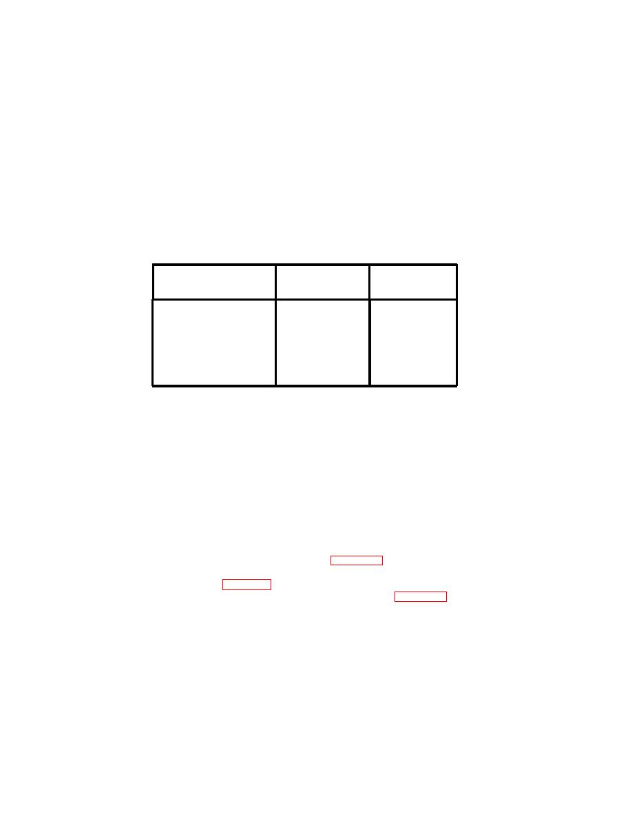
Unsolder wires from three BNC connectors as shown In table below.
BNC CONNECTOR
INDEX
WIRE
NUMBER
NUMBER
COLOR
13
J1
BRN
14
BLK
15
J2
WHT
16
BLK
17
J3
GRN
BLK
18
Remove wire harness (6) from chassis.
8.
INSTALLATION
1.
Solder wires to three BNC connectors as shown in table above.
Install two loop clamps (12) on wire harness (6).
2.
Install two screws (9), flat washers (10), and locknuts (11).
3.
Position channel (8) on chassis and install three screws (7) through bottom of
4.
chassis.
Route wire harness (6) as shown in illustration and install tie wrap (5).
5.
Plug connector P7 (3) into A6AT1 assembly (4).
6.
Plug connector J4 (2) and connector P6 (1) into front panel A1.
7.
FOLLOW-ON MAINTENANCE: Install power supply A5 (para 2-34).
Install rf modulator assembly A3 and synthesizer assembly A4
Install controller/audio assembly A2 (para 2-35).
2-61
|
|
Privacy Statement - Press Release - Copyright Information. - Contact Us |
