 |
|||
|
|
|||
|
|
|||
| ||||||||||
|
|
 TM 11-6625-2975-40
2-22.
POWER SUPPLY ALINEMENT. (CONT)
EL9LY066
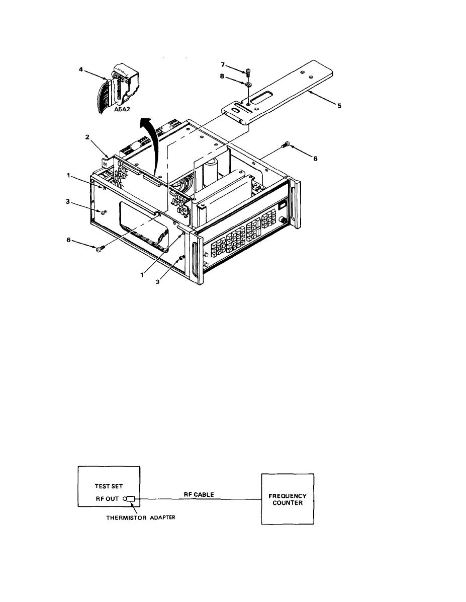
23. Loosen two top turn-lock fasteners (1) and lower assembly A2 (2) to aline bottom holes of
assembly A2 with two bottom turn-lock fasteners (3).
24. Tighten two bottom turn-lock fasteners (3) and two top turn-lock fasteners (1).
25. Plug connector PI (4) into A5A2 assembly.
26. Position top bracket (5) in chassis and install four screws (6) through sides of chassis.
27. Install four screws (7) and Iockwashers (8) through top bracket (5).
TEST EQUIPMENT REQUIRED: Adapter, N plug-to-BNC jack
Frequency Counter HP 5345A
RF Cable RG-58/U
EQUIPMENT SETUP: Connect test set to 115 vac power source.
Connect frequency counter to test set as indicated in the following diagram.
EL9LY011
|
|
Privacy Statement - Press Release - Copyright Information. - Contact Us |
