 |
|||
|
|
|||
|
|
|||
| ||||||||||
|
|
 TM 11-6625-2975-40
2-12. GLIDE SLOPE DDM PERFORMANCE TEST. (CONT)
PROCEDURE
1.
Enter frequency 335.00 MHz into test set.
Extinguish 150 Hz TONE SELECT key and record W-HZ differential voltmeter indication. (If 90 Hz
2.
key not lit, press to light.)
3.
Extinguish 90 Hz TONE SELECT key and press (to light) 150 Hz TONE SELECT key.
4.
Record 150Hz differential voltmeter indication.
Divide value recorded in step 2 by value recorded in step 4. Resulting voltage ratio should be
5.
between 0.99975 and 1.00025. If not, go to troubleshooting chart 2-1, sh 9.
Disconnect differential voltmeter from test set COMP connector and connect to DEMOD
6.
connector.
7.
Repeat steps 2 through 5. Voltage ratio should be between 0.99745 and 1.00255. If not, go to
troubleshooting chart 2-1, sh 9.
Disconnect differential voltmeter from test set DEMOD connector.
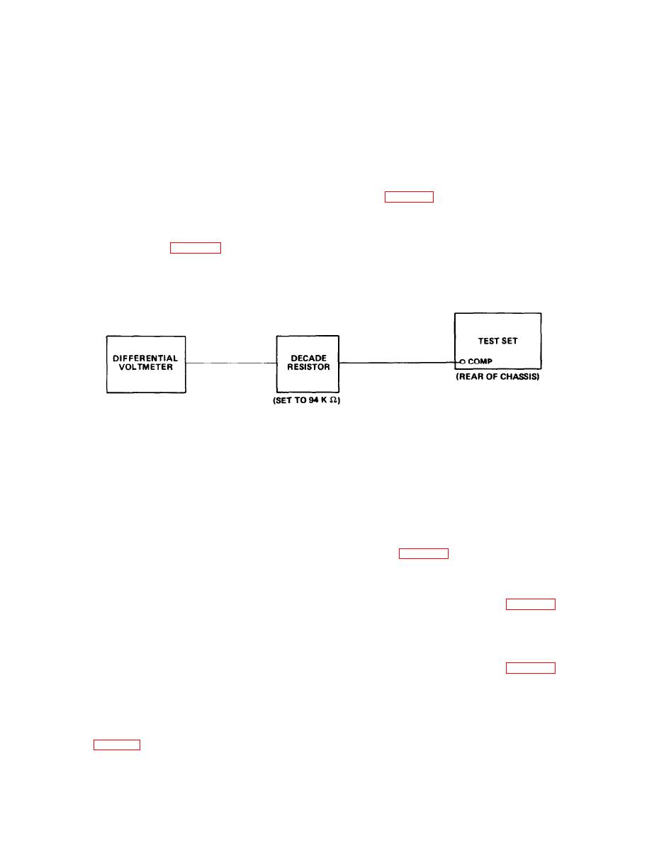
8.
Connect equipment as indicated in the following diagram.
9.
EL9LY018
Press and release STEP ∆ RDL ∆ DDM FUNCTION/CONTROL key. RDL/DDM/MOD display will
10.
indicate .045.
11.
Extinguish 150 Hz TONE SELECT key and press (to light) 90 Hz TONE SELECT key. Record
W-HZ differential voltmeter indication.
12.
Extinguish 90 Hz key and press (to light) 150 Hz key.
13.
Record 150-Hz differential voltmeter indication.
14.
Divide value recorded in step 13 by value recorded in step 11. Resulting voltage ratio should
be between 1.11864 and 1.11979. If not, go to troubleshooting chart 2-1, sh 9.
Press and release STEP ∆ RDL ∆ DDM FUNCTION/CONTROL key. RDL/DDM/MOD display will
15.
indicate .091.
Repeat steps 11, 12, and 13. Divide value recorded in step 13 by value recorded in step 11.
16.
Voltage ratio should be between 1.25806 and 1.25733. If not, go to troubleshooting chart 2-1,
sh 9.
Press and release STEP ∆ RDL ∆ DDM FUNCTION/CONTROL key. RDL/DDM/MOD display will
17.
indicate.175.
Repeat steps 11, 12, and 13. Divide value recorded in step 13 by value recorded in step 11.
18.
Voltage ratio should be between 1.55918 and 1.56082. If not, go to troubleshooting chart 2-1,
sh 9.
Press and release STEP ∆ RDL ∆ DDM FUNCTION/CONTROL key. RDL/DDM/MOD display will
19.
indicate .400.
Repeat steps 11, 12, and 13. Divide value recorded in step 13 by value recorded in step 11.
20.
Resulting voltage ratio should be between 2.99800 and 3.00200. If not, go to troubleshooting
chart 2-1, sh 9.
2-13
|
|
Privacy Statement - Press Release - Copyright Information. - Contact Us |
