 |
|||
|
|
|||
|
Page Title:
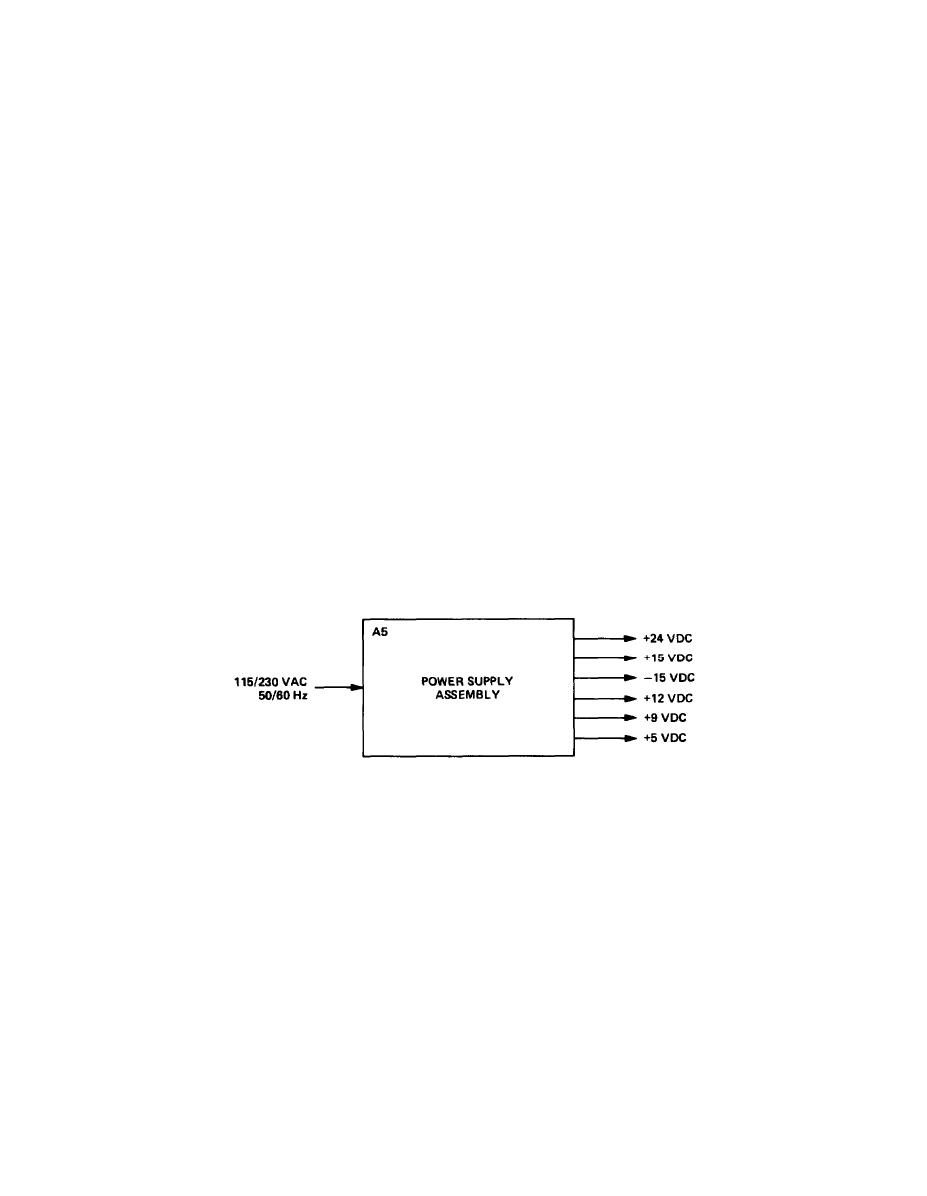
POWER SUPPLY ASSEMBLY OPERATION. |
|
||
| ||||||||||
|
|
 TM 11-6625-2975-40
1-18. RF SECTION OPERATION. (CONT)
The rf strip line assembly A3A1 produces a signal that is the rf carrier frequency. It also produces a
demodulated signal which is the modulated signal with the rf carrier removed, The rf signal is supplied
to the counter I/O board A3A3 and the demodulator signal to demodulator/ale assembly A3A2.
Counter l/O board A3A3 counts the rf signal to determine the output signal frequency. This information
Is supplied to the counter l/O board A3A3 output ports. When the cpu requests the frequency count,
this information is supplied to the cpu through the control bus. The cpu uses this frequency count to
supply frequency information to be displayed in the FREQUENCY display of the front paneI. When
requested by the cpu, counter l/O board A3A3 supplies phase-lock information from the I/O port over
the control bus. The cpu uses this information to supply data to the front panel assembly for the control
of RF STATUS-PH LOCK indicator.
The demodulator signal from rf strip line assembly A3A1 is supplied to demodulator/ale assembly
A3A2. This signal is used to level the rf carrier and to linearize the modulation signal supplied to rf strip
line assembly A3A1. The demodulation signal is also supplied to the DEMOD connector on the rear
panel. When the rf output is within specified limits, a calibration signal is supplied to an l/O port on
counter I/O board A3A3. This calibration status information is continually being sampled and the
information returned over the control bus to the cpu. The cpu uses this calibration status information
for supplying data to the front panel assembly RF STATUS-LEVEL CAL indicator.
.
EL9LY010
The test set can operate on either 115 or 230 vac, 50/60 Hz power supply. The power supply assembly
produces + 24, + 15,-15, + 12, +9, and + 5 vdc for the test set operation.
1-15/(1-16 blank)
|
|
Privacy Statement - Press Release - Copyright Information. - Contact Us |
