 |
|||
|
|
|||
|
Page Title:
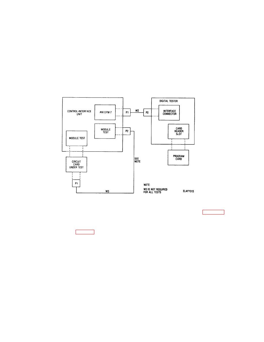
Figure 2-9. Typical standard logic card test connections |
|
||
| ||||||||||
|
|
 TM 11-6625-2937-13
DEC or STE) and observe MODULE TEST ON indicator
(11) Press either TEST switch-indicator on
lights.
digital tester to down position and observe indicator
(7) Insert applicable program card in card
lights.
reader slot of digital tester.
(a) Observe TEST NUMBER display on
(8) Press PROGRAM ENTER switch-indicator
control-interface unit for proper program card test.
on digital tester to down position and observe that
(b) Observe that MODE IN ERROR
PROGRAM ENTER indicator lights. Observe READY
indicator does not flash.
indicator on digital tester lights after approximately 10
(c) Observe that TEST ON indicator on
seconds and PROGRAM ENTER indicator goes off.
control-interface unit fights during program card test and
(9) Set TEST RATE PER SEC switch on digital
goes out at end of test.
tester in accordance with program card test.
(d) Observe PASS/FAIL indicator on
(10) Set NUMBER OF TESTS switch on digital
digital tester lights PASS or FAIL.
tester in accordance with program card test.
(12) Set control-interface unit and digital tester
controls to their OFF position.
Figure 2-9. Typical standard logic card test connections
g. Shutdown Procedure. To shut the test set
of preventive maintenance (table 3-1) should be
increased to daily to avoid equipment breakdown.
group down after the desired tests have been performed
(2) Extreme dry heat. When the test set group
proceed as follows:
is operated in extreme dry heat over prolonged periods
(1) Set all controls on control-interface unit and
of time, connecting cables and connectors should be
digital tester in accordance with table 2-4.
inspected weekly for cracks or breaks.
(2) Remove all connecting cables and
(3) Extreme cold. When the test set group Is
adapters, except input power cables, that were used
during tests. Stow these accessories in the cover of the
being operated in low temperatures (arctic climates) over
test set case or in a convenient work bench drawer or
prolonged periods of time, the frequency of preventive
cabinet.
maintenance (tables 3-1 and 3-2) should be increased to
daily to avoid equipment breakdown.
2-6.
Operation Under Unusual Conditions
(4) Salt air and sea spray. The test set group
a. Operation Under Extreme Environmental
should not be exposed to these conditions over
Conditions. The test set group is designed as an all
prolonged periods of time as rust, corrosion and
weather equipment. However, extreme temperatures
component breakdown may result
and weather conditions can affect equipment
(5) Sandstorms or duststorms. Dust or sand
performance.
are major problems in desert areas Frequent dusting and
(1) Extreme moist heat. When the test set
clean-
group is operated in extreme moist heat (tropical
climates) over prolonged periods of time, the frequency
2-12
|
|
Privacy Statement - Press Release - Copyright Information. - Contact Us |
