 |
|||
|
|
|||
|
Page Title:
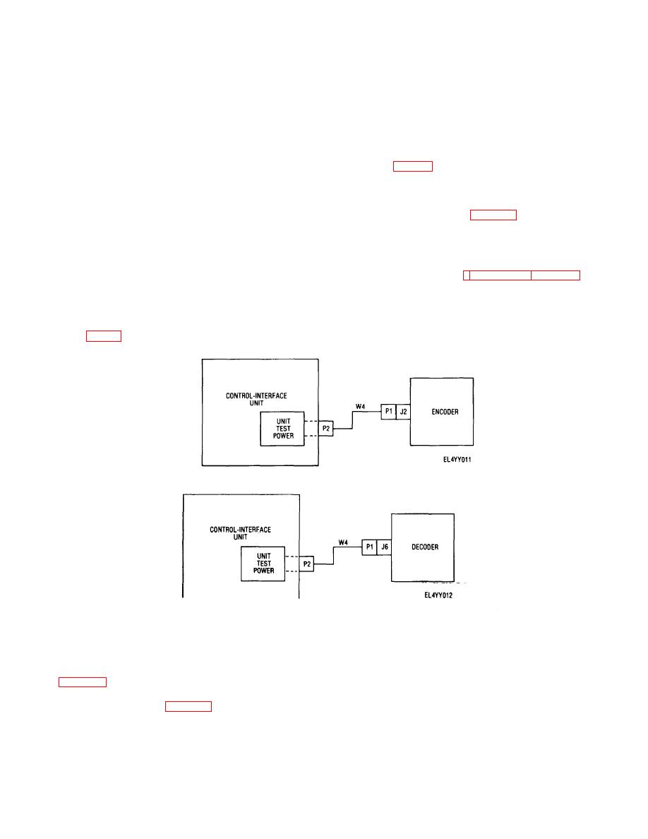
Figure 2-7. Interconnections for encoder unit tests. |
|
||
| ||||||||||
|
|
 TM 11-6825-2937-13
oscilloscope from pin H2 and F8 (gnd) of MODULE
tester to down position and observe the following:
1. TEST switch indicator on digital tester
TEST connector.
5. Reconnect channel B of oscilloscope
lights.
2. TEST ON indicator on control-interface unit
between pin H7 and F8 (gnd) of MODULE TEST
connector.
lights.
6. Adjust oscilloscope controls so that
3. All MODE/POWER indicators on control-
waveforms displayed clearly show displacement between
interface unit flash twice and TEST NUMBER indicates
signals monitored. Displacement should be less than
88.8.
4. At end of BITE test, TEST NUMBER
100 ns (B, fig. 5-2).
7. Remove oscilloscope leads from MODULE
indicator reads 00.5.
5. PASS indicator on digital tester fights at the
TEST connector.
(f) Set control-interface unit and digital tester
end of test.
(e) Perform phase-displacement check as
controls in accordance with table 2-4.
d. Digital Tester Self Test. To perform a
follows:
1. On the control-interface unit, connect
digital tester self test, refer to TM 11-6625-2951-13.
e. General Operating Procedures. A typical
channel A of oscilloscope between pin HI and pin FS
procedure for performing a standard logic card test is
(gnd) of MODULE TEST connector.
2. Connect channel B of oscilloscope between
interconnections for encoder and decoder unit tests,
pin H2 and pin FS (sod) of MODULE TEST connector.
3. Adjust oscilloscope controls so that
respectively. For detailed procedures for performing unit
tests and microprocessor, standard logic and analog
waveforms displayed clearly show displacement between
circuit card tests, refer to TM 11-5841-287-30 (encoder)
signals monitored. Displacement should be less than
and TM 11-5840-361-30 (decoder).
100 ns (A, fig 5-2).
4. Disconnect
channel
B
of
Figure 2-7. Interconnections for encoder unit tests.
Figure 2-8. Interconnections for decoder unit tests.
f.
Typical Standard Logic Card Test. To
POWER and PROGRAM ERROR (red) indicators fight.
(4) Place UUT POWER switch-indicator on
perform a typical standard logic card test on a decoder
digital tester to up position (N) and observe that UUT
card proceed as follows:
POWER indicator lights.
(1) Interconnect test set group in accordance
(5) Place POWER ON/OFF switch on control-
with figure 2-9.
interface unit to ON and observe that POWER ON
(2) Set control-interface unit and digital tester
indicator lights.
controls in accordance with table 2-4.
(6) Place MODE SELECT switch on control-
(3) Place POWER switch-indicator on digital
interface unit to applicable MODULE TEST position
tester to up position (ON) and observe that
(ENC,
2-11
|
|
Privacy Statement - Press Release - Copyright Information. - Contact Us |
