 |
|||
|
|
|||
|
|
|||
| ||||||||||
|
|
 TM 11-6625-2885-30/NAVAIR 16-35TS3614-2
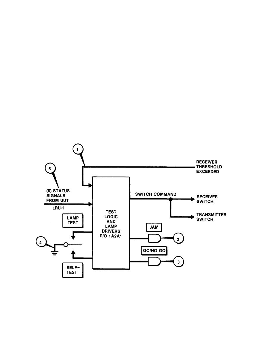
TEST LOGIC AND LAMP DRIVING
In the following description, SLL O is a signal between 0.0 and +0.6
2-5.
volts. SLL 1 is a signal between +2.4 and +5.0 volts. Normal operation
of the FLTS tests a CM set. A normal RF level from the CM set transmit
antenna causes a SLL O Receiver Threshold Exceeded Signal (1) in the FLTS
receiver assembly. This SLL O signal lights a JAM indicator (2) in the
FLTS video assembly.
The FLTS transmitter assembly sends test signals to the CM set receive antenna.
Normal CM set response to these signals sets six LRU-1 status signals (5) to
SLL O. When these six status signals and the Receiver Threshold Exceeded
Signal are all at SLL O, they light a GO/NO GO indicator (3) in the FLTS video
assembly.
In self-test operation, jumper cable W4 sends RF from the transmitter assembly
to the receiver assembly. The test logic circuits receive a threshold exceeded
signal (1) from the receiver assembly which lights the JAM lamp (2) and enables
the GO/NO GO lamp (3). In self-test, the JAM light confirms the RF level at
the FLTS transmitter. The test switch (4) replaces the status signals (5),
lighting the GO/NO GO lamp.
|
|
Privacy Statement - Press Release - Copyright Information. - Contact Us |
