 |
|||
|
|
|||
|
|
|||
| ||||||||||
|
|
 TM 1l-6625-2884-30/NAVAIR 16-35TS3615-2
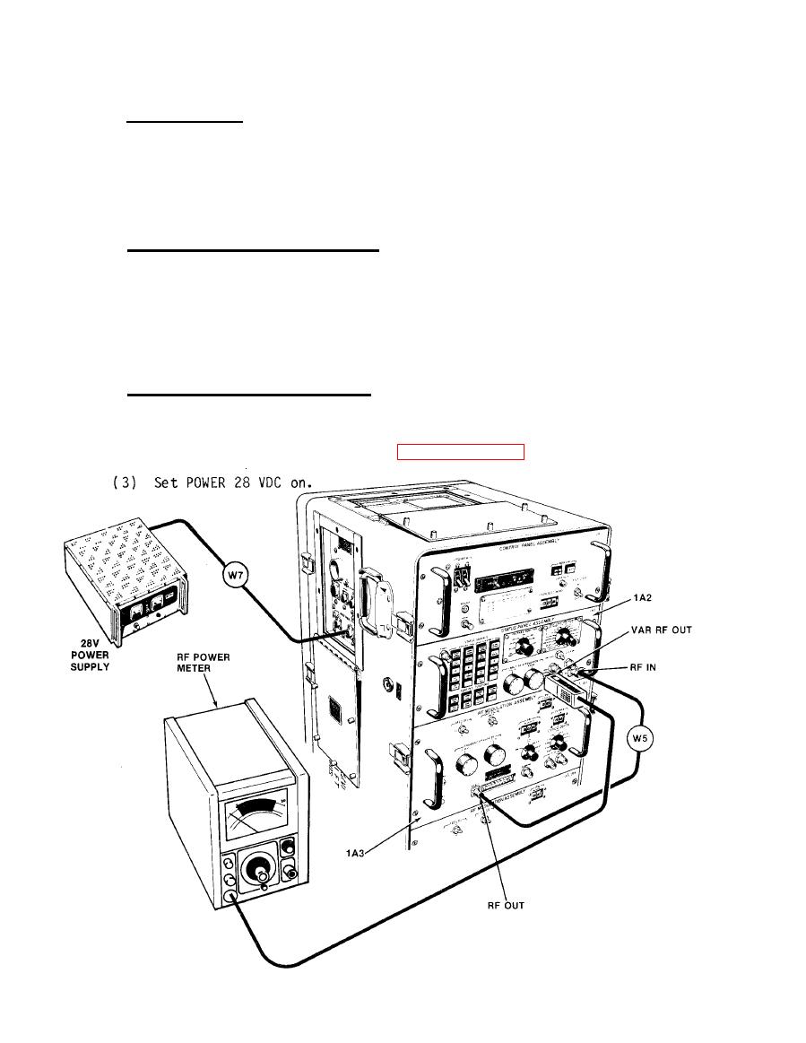
YIG FILTER CHECK
3-27
a. Test Equipment.
RF Power Meter HP 435A
RF Power Sensor HP 8481A
28 Vdc Power Supply PP-1104( )/G
b.
Test Connections and Conditions.
(1) Connect RF Cable W5 from RF Modulation Assembly 1A3 RF OUT jack
to RF IN jack on status panel.
(2) Connect RF power meter sensor to VAR RF OUT jack on status panel.
(3) Connect W7 to 28 Vdc power supply.
c.
Initial Test Equipment Setting.
(1) Set RF power meter to +10 dBm scale.
(2) Other equipment settings are as paragraph 3-14.
3-62
|
|
Privacy Statement - Press Release - Copyright Information. - Contact Us |
