 |
|||
|
|
|||
|
|
|||
| ||||||||||
|
|
 TM 11-6625-2884-30/NAVAIR 16-35TS3615-2
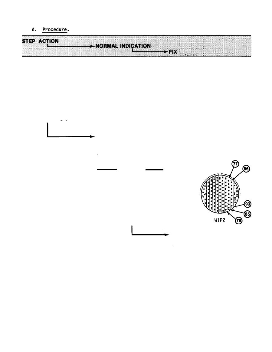
Connect negative lead of
1.
ohmmeter to V MON jack
J6 and the positive lead
to the following cable
W1P2 pins and check for
continuity as the status
panel VOLTAGE MONITOR
switch is set to the
following positions.
Each continuity measurement
2.2K 1O% for the following:
VOLTAGE
MONITOR
W1P2
SWITCH
PIN NO
+5V LOGIC
77
+ 5V
78
-5.2V
79
+1OV
80
-1OV
86
+15V
87
-15V
88
+28V
83
-65V
89
If measurement is not
2.2 K +10% it probably
is indicated by an
infinite reading, which
means an open R2 or an
open in one of the two
connectors or in the J1
female receptacle on
the connector panel at
the left side of the
bench test set. Care-
fully probe and repair
any defect at the BTS
jack, or at either
connector of Cable W1.
END OF TEST
3-61
|
|
Privacy Statement - Press Release - Copyright Information. - Contact Us |
