 |
|||
|
|
|||
|
|
|||
| ||||||||||
|
|
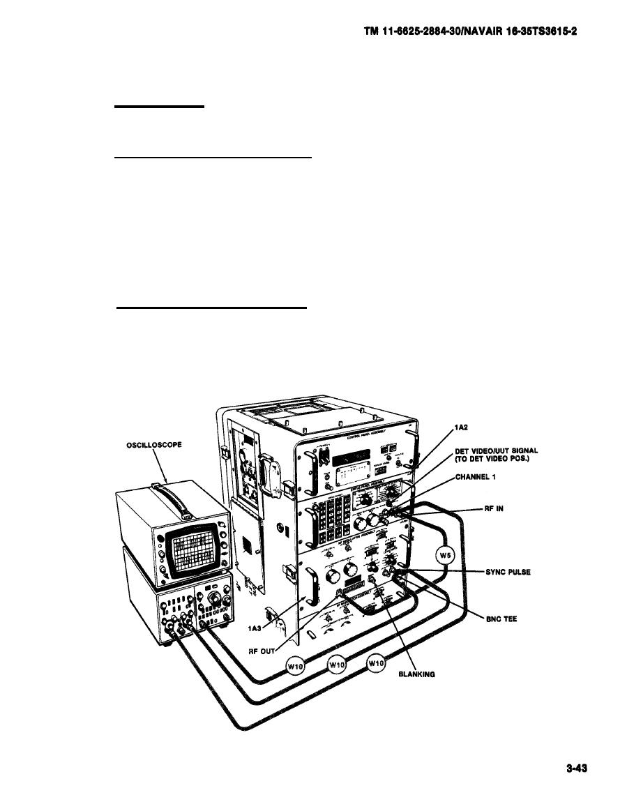 PULSE SYNC TEST
3-21.
a. Test Equipment.
Oscilloscope AN/USM-281A.
b.
Test Connections and Conditions.
(1) Connect RF Cable W5 from RF OUT jack on RF Modulation Assembly 1A3
to RF IN jack on status panel.
(2) Install a BNC tee connector at SYNC PULSE jack of RF Modulation
Assembly 1A3. Connect one side of BNC tee to oscilloscope EXT input.
de of BNC tee to oscilloscope B input.
(3) Set switch to DET VIDEO on status panel. Connect CHAN 1 to
oscilloscope A Input.
c. Initial Test Equipment Setting.
(1) On oscilloscope time base and delay generator, set POS/NEG push-
button switch to NEG.
|
|
Privacy Statement - Press Release - Copyright Information. - Contact Us |
