 |
|||
|
|
|||
|
|
|||
| ||||||||||
|
|
 TM 11-6625-2884-30/NAVAIR 16-35TS3615-2
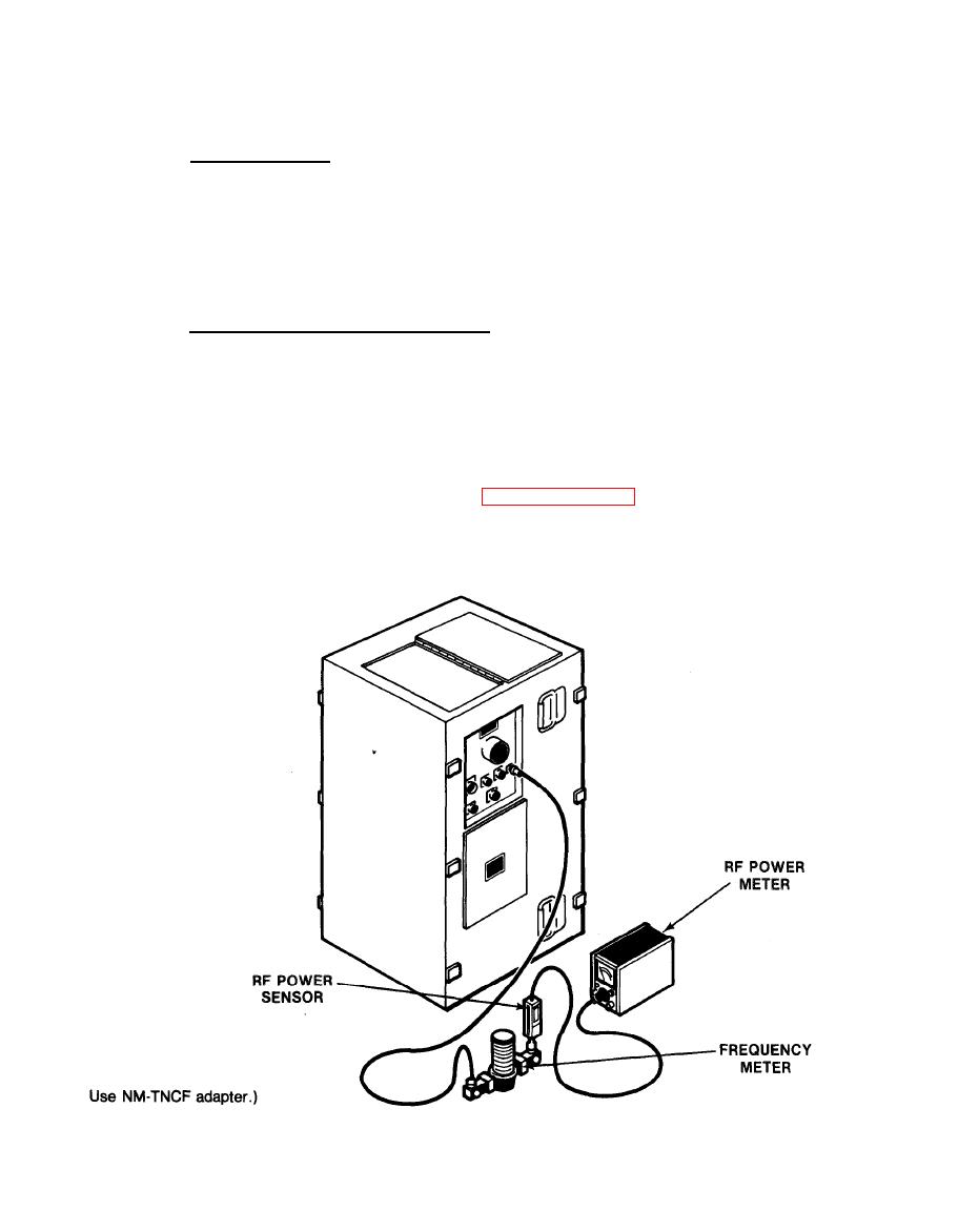
RF OUTPUT FREQUENCY CHECK
3-16.
a.
Test Equipment.
Frequency Meter
HP P532A
with adapters
RF Power Meter
HP 435A
Power Sensor
HP 8481A
b.
Test Connections and Conditions.
(1) Make sure all chassis units are in place, and all internal cables
are connected. Turn on 115 V ac power.
(2) Warm-up for 30 minutes.
c.
Initial Test Equipment Setting. Set the RF power meter to a full
scale range, approximately 5 dB above the normal indication (0 dBm full
scale). Other controls are as in paragraph 3-14a.
d.
Reference Material. See (S) TM 11-5865-202-30(U) for frequency data where
1, F2 and F3 is referenced in procedures. Schematics of this equipment
are in foldout illustrations at the rear of this manual.
3-19
|
|
Privacy Statement - Press Release - Copyright Information. - Contact Us |
