 |
|||
|
|
|||
|
|
|||
| ||||||||||
|
|
 TM 11-6625-2884-30/NAVAIR 16-35TS3615-2
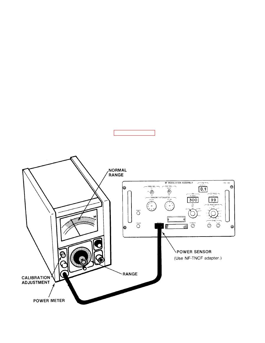
RF OUTPUT LEVEL CHECK
Test Equipment. Use the following test equipment or equivalent to
a.
troubleshoot the RF section of RF Modulation Assemblies 1A3/1A4.
RF POWER METER HP435A
RF POWER SENSOR HP8481A
b.
Test Connections and Conditions.
(1) Make sure all chassis units are in place and all internal cables
are connected.
(2) Connect RF power sensor to RF OUT jack on upper RF modulation
assembly 1A3.
Initial Test Equipment Setting. Set the RF power meter to a full scale
c.
range 5 dB above the normal indication (+10 dBm full scale). Other
equipment settings are as in paragraph 3-14a.
3-14
|
|
Privacy Statement - Press Release - Copyright Information. - Contact Us |
