 |
|||
|
|
|||
|
|
|||
| ||||||||||
|
|
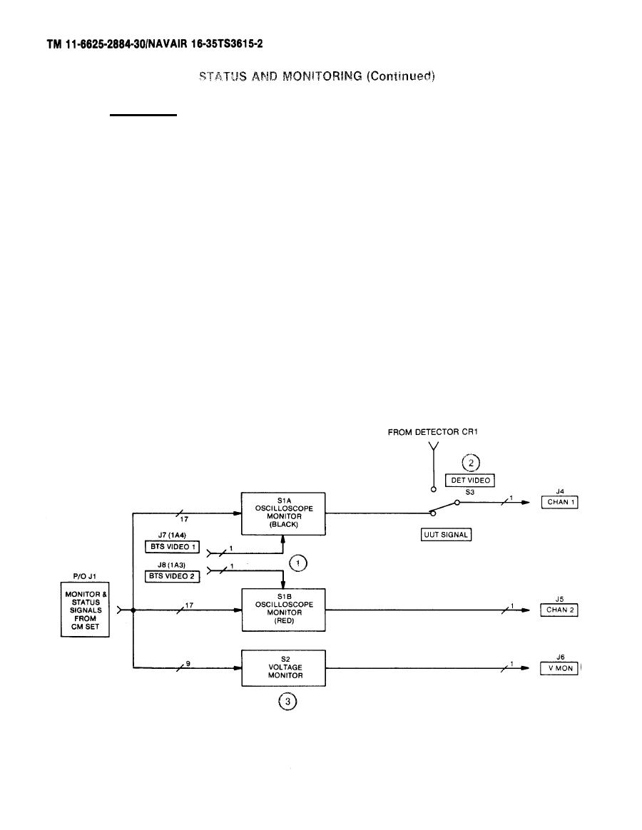 b.
Monitoring.
OSCILLOSCOPE MONITOR (BLACK) S1A and OSCILLOSCOPE MONITOR (RED)
(1)
S1B. This dual concentric rotary switch receives a total of 17
pulsed or varying system monitor signals from LRU-1 jack J7,
connected through cable W1 to jack J1 on the status panel. The
switch also receives the BTS VIDEO 1 (J7) from RF Modulation
Assembly 1A4 and BTS VIDEO 2 (J8) from RF Modulation Assembly 1A3.
The rotary switch black knob switches CHAN 1 connector J4 to one of
17 points in LRU-1 or to BTS VIDEO J7. The rotary switch red knob
switches CHAN 2 (J5) to one of 17 points in the UUT or the BTS
VIDEO J8.
DET VIDEO/UUT SIGNAL S3. This toggle switch selects either the de-
(2)
tected video from CR1 in the RF path or the signal being monitored
by OSCILLOSCOPE MONITOR (BLACK) S1A and directs it to CHAN 1 con-
nector J4.
VOLTAGE MONITOR S2. Nine DC voltages from the low voltage power
(3)
supply in LRU-1 are connected through LRU-1 J7, Cable W1, to status
panel jack J1. The voltages are selectable by VOLTAGE MONITOR
Switch S2 on the front panel for measurement with an external digi-
tal multimeter connected to V MON J6.
2-38
|
|
Privacy Statement - Press Release - Copyright Information. - Contact Us |
