 |
|||
|
|
|||
|
|
|||
| ||||||||||
|
|
 TM 11-6625-2884-30/NAVAIR 16-35TS3615-2
LINEAR MODULATION
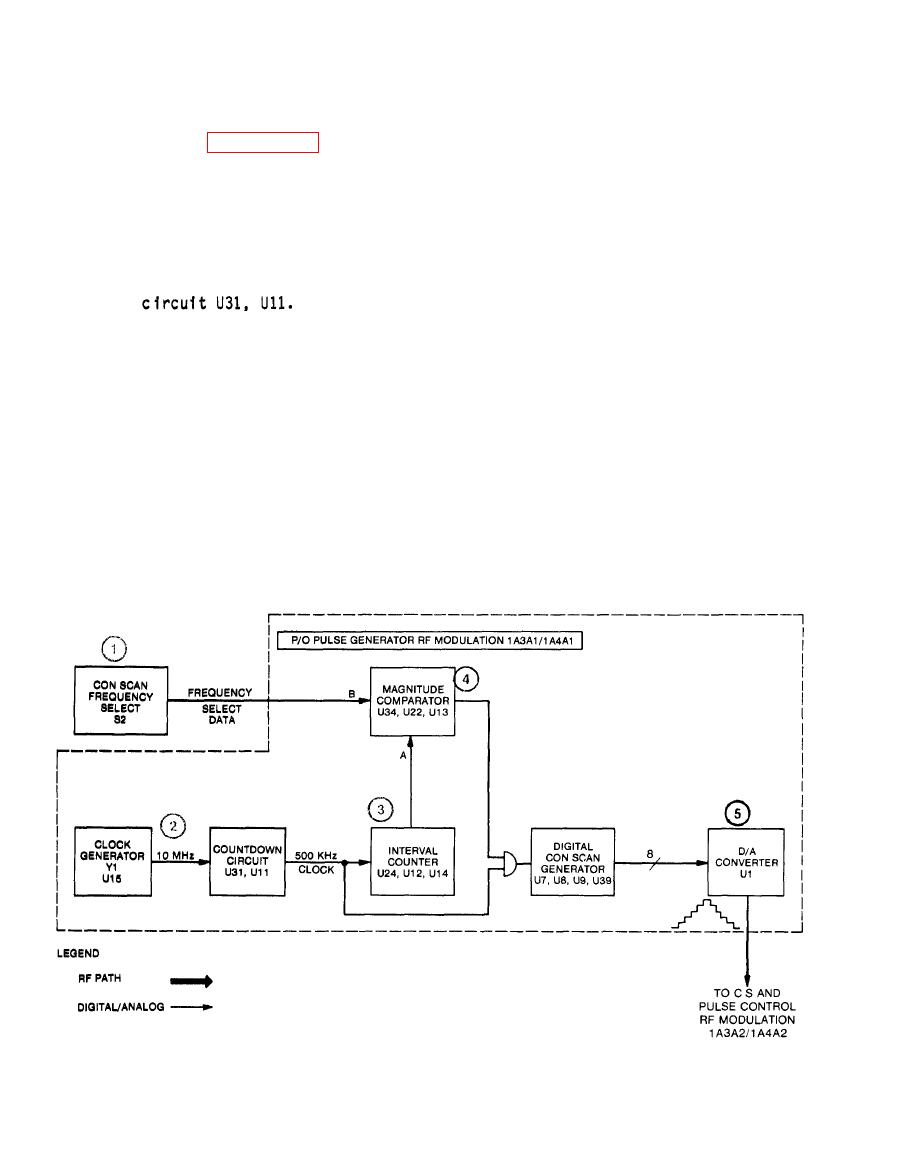
generator located on circuit cards 1A3A1/1A4A1 and 1A3A2/1A4A2. This generator
develops an audio sinewave which drives the linear modulator to amplitude
modulate the RF signal.
selects the con scan frequency in 1 Hz steps from 1 Hz to 99 Hz.
(2) CLOCK GENERATOR Y1 (U15) is a 10 MHz oscillator which feeds countdown
(3) The output of countdown circuit is a 500 KHz clock which steps the
interval counter U24, U12, U14.
data with the count in the interval counter. When a comparison occurs
the digital con scan generator U7, U8, U9, U39 is loaded and the inter-
val counter is reset.
(5) The output of the DIGITAL CON SCAN GENERATOR is in 8-bit parallel
binary form. The D/A Converter U1 changes the digital data to a
triangle wave.
2-34
|
|
Privacy Statement - Press Release - Copyright Information. - Contact Us |
