 |
|||
|
|
|||
|
|
|||
| ||||||||||
|
|
 TM 11-6625-2884-30/NAVAIR 16-35TS3615-2
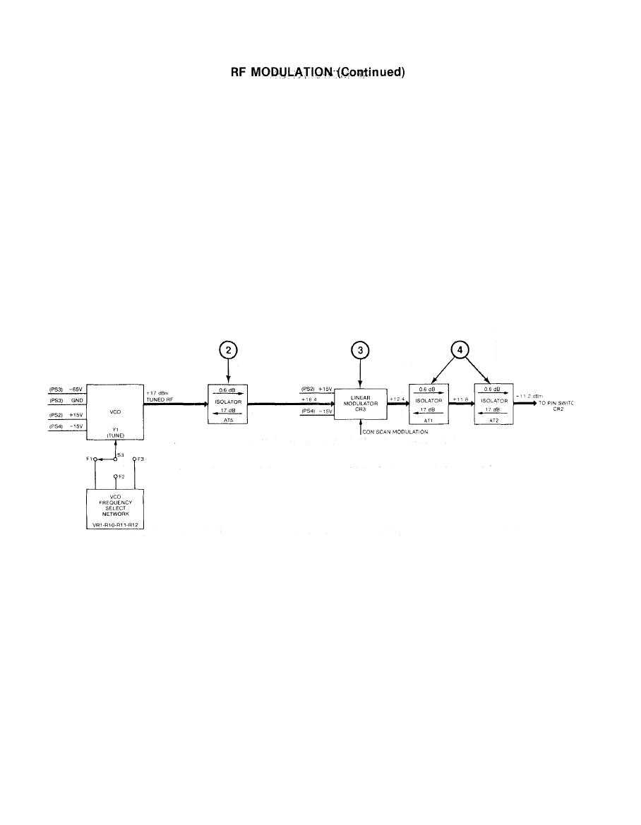
(2) ISOLATOR AT5 provides a constant loading to the VCO and prevents
RF reflections from the linear modulator.
(3) LINEAR MODULATOR CR3 is an absorptive pin diode modulator with
integral drivers. The linear modulator is used to amplitude
modulate the RF signal from the VCO with the threat amplitude
The minimum insertion loss is 4 dB. The modu-
characteristics.
later has the capability of increasing the attenuation above this
insertion loss by 60 dB. The con scan modulation control can vary
the attenuation between O dB and 25 dB.
(4) ISOLATORS AT1 and AT2 provide a constant loading to the linear
modulator and prevent any RF reflections from Pin Switch CR2.
(5) PIN SWITCH CR2 is a pin diode SPST switch and associated driver.
When enabled, the RF signal is pulse modulated at the rate of the
pulse drive input. The maximum attenuation is 70 dB plus 3 dB
insertion loss. The control voltage to the switch (PULSE DRIVE) is
a standard logic level (SLL) signal. A logic one (2.4V to 5V)
places the switch in its maximum attenuation condition. A logic
zero (0.OV to 0.6V) places the switch in its minimum attenuation
state. The pin switch is capable of switching from maximum to
minimum attenuation or from minimum to maximum attenuation within
50 nanoseconds.
2-44
|
|
Privacy Statement - Press Release - Copyright Information. - Contact Us |
